
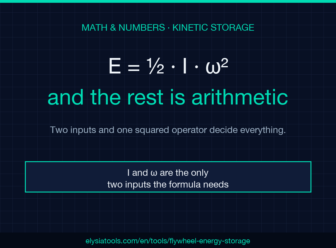
Pick the right pair — rotational speed and moment of inertia — and the rest is arithmetic. A flywheel stores energy because a spinning mass refuses to stop, and the formula E = ½·I·ω² makes that refusal exactly quantifiable. The calculator at Elysia Tools returns that number in joules, kilojoules, or watt-hours from just two inputs. This guide walks through when each input is the binding constraint, why I and ω sit on opposite sides of a squared operator, and how to read the answer back as something the datasheet actually quotes.
Why Energy Storage Matters in a Spinning Disc
The kinetic energy of a rotating rigid body lives entirely in the rotation, not in any displacement. That property is what makes flywheels useful as short-duration buffers between a prime mover and a load: they absorb and release energy without chemistry, without phase change, and without moving parts in contact. The trade is that the energy scales with ω², not linearly, so doubling the spin rate quadruples the storage. That nonlinearity shapes the design space more than any other single parameter.
For grid-scale UPS systems, the same physics lets a 200 kg steel rotor running at several thousand rpm deliver megajoules of stored work in a brownout — enough ride-through time for a diesel generator to come up to speed. The total energy is small compared to a battery bank, but the discharge rate is enormous.
When I Is the Limiting Number
The moment of inertia is the harder input to estimate because it depends on geometry. A solid disc, a hollow cylinder, and a thin rim store dramatically different amounts of kinetic energy at the same spin rate, even with the same mass. The flywheel calculator accepts I directly, which is the right choice when you have a CAD model, a manufacturer’s datasheet, or a known geometry like a solid disc where I = ½·m·r². Plugging in that derived value beats guessing.
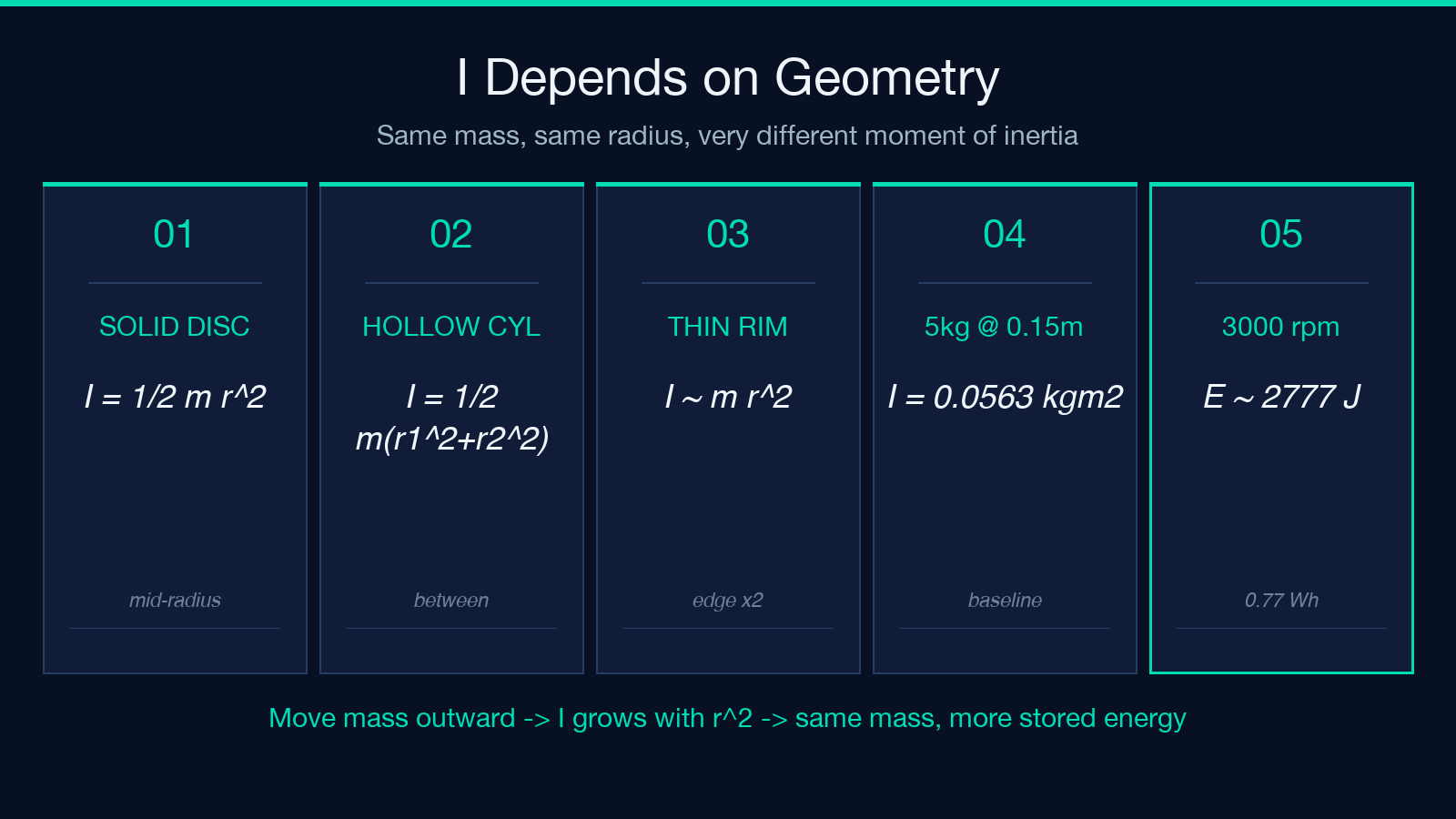
For a steel disc of 5 kg at radius 0.15 m, I = ½·5·0.15² = 0.0563 kg·m². Spinning that at 3000 rpm gives ω = 2π·3000/60 ≈ 314.16 rad/s, so E = ½·0.0563·314.16² ≈ 2777 J ≈ 0.77 Wh. A rim-weighted flywheel of the same mass and diameter stores nearly twice as much because more of the mass sits far from the axis — the r² dependence rewards you for moving mass outward.
When ω Is the Limiting Number
If the rotor is constrained by a maximum safe rpm (bearing speed, balancing grade, hoop-stress limits), the energy scales linearly with ω². Doubling the spin speed quadruples the stored energy, but it also quadruples the centrifugal stress. Most commercial flywheels for grid energy storage run between 10000 and 60000 rpm on magnetic bearings, while smaller lab and exercise flywheels live below 5000 rpm.
For the same I = 0.0563 kg·m² used above, raising the speed from 3000 rpm to 6000 rpm takes the energy from 0.77 Wh to 3.1 Wh — a fourfold jump from a single geometric input change. This is why high-speed flywheels look so attractive on paper and so expensive in practice.
Translating J to kJ to Wh Without Rounding Errors
The calculator returns energy in three units, and the right one depends on context. Watts and watt-hours dominate electrical datasheets; joules dominate mechanical engineering; kilojoules dominate HVAC. A 100 Wh rating sounds consumer-grade; the same energy reads as 360 kJ, which sounds industrial. Same number, different framing.

Switching units mid-derivation is a common source of bugs. If your motor controller expects watt-hours but the spec sheet reports joules, drop the unit explicitly before comparing. The calculator’s unit toggle keeps the math correct; just make sure your downstream code reads the same unit you selected.
Worked Example: From Inputs to a Datasheet-Ready Number
Take I = 2 kg·m² at 3000 rpm. The calculator returns ω = 314.1593 rad/s and E = ½·2·314.16² = 98696.044 J. That reads as 98.7 kJ or 27.4 Wh on the same screen, and matches what you would compute by hand to four decimal places. The output JSON carries both the symbolic derivation and the numeric result, so the same answer slots into a LaTeX report, a Jupyter cell, or a vendor spec without manual re-derivation. The full result lives in the JSON payload that the calculator returns; piping it straight into a plotting library is a single line of code.
If your real input is mass and radius rather than I directly, the calculator derives I from those primitives using the solid-disc approximation, then continues with the same E = ½·I·ω² step. For rim-weighted rotors the effective I is closer to m·r², so you would override the derived value with the explicit one you trust.
When the Formula Breaks Down
E = ½·I·ω² assumes a rigid rotor with constant I. Composite rotors, variable geometry, and gyroscopic coupling at high speed all violate those assumptions, sometimes by a small enough margin to ignore and sometimes not. If your flywheel is a flywheel-battery hybrid with a vacuum chamber and magnetic levitation, the spin-down losses show up in the J/s column, not in this static formula. Use this calculator for steady-state energy and reach for a time-dependent model when the answer has to track losses.
The math also assumes a single rigid body. A flywheel coupled to a shaft that flexes under load behaves like two inertias in series, and the effective I for the energy-storage calculation is the rotor’s I alone — not the shaft’s contribution. Practical rotors live in the regime where the rotor dominates, but at low speeds with a heavy shaft the shaft’s inertia can absorb a non-trivial fraction of the kinetic energy.
Three Pitfalls When Reading the Result Back
The calculator prints E, ω, and I together, but the output is only as good as the inputs. The three failure modes that show up most often in practice are: using the wrong rpm units (revolutions per second vs revolutions per minute — a factor of 60), reading the rotational speed as a tip speed (rim velocity scales with r, not ω), and forgetting that I in the formula is about the rotor axis specifically, not the system axis.
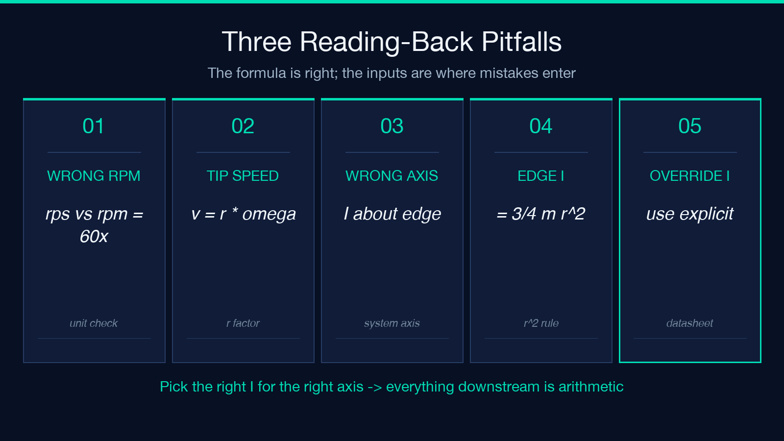
A disk that spins about its own center has I = ½·m·r²; the same disk spinning about a parallel axis through its edge has I = ¾·m·r². The calculator assumes the first case when you pass mass and radius. If your real rotor spins about a different axis, override I directly with the formulation that matches your mounting.
A Closing Note on Picking the Right ω
The fastest path to a wrong answer in flywheel sizing is to assume a single characteristic speed. Industrial UPS flywheels and laboratory rotors share the same formula but operate at very different ω, and the resulting energy differs by orders of magnitude. Take the speed from the same source as the mass and radius — a CAD model, a datasheet, or a measured tachometer reading — and feed all three numbers into the flywheel energy storage calculator. The answer in joules is one click, and reading it back in watt-hours turns the same number into a battery-spec comparison without re-deriving anything.
