
The U-value is only as honest as the layer list you hand it. Add the convection film on both sides, fold in fouling once the loop has run a season, and the wall that looked like 1.9 W/(m·K) on day one quietly degrades to 1.1 by month nine. The flat-wall 1/U = ΣR model is small, exact, and merciless — it surfaces every missing layer as a lower Q or a higher wall temperature than the datasheet promised.
The Overall Heat Transfer Coefficient calculator takes any number of per-layer resistances in K/W (each already containing its area factor), an area in m², and an optional ΔT, then reports R_total, thermal conductance G, U in W/(m²·K), and the heat flow rate Q in watts. The output is one flat JSON object with every intermediate kept — useful for verifying a hand calculation, populating a building-envelope spec sheet, or sanity-checking a heat-exchanger selection.
Why the flat-wall 1/U = ΣR formula still wins for engineering checks
Most heat-transfer tooling offers the cylindrical-pipe log-mean form by default. That is the right call for a chilled-water coil, but it is the wrong one for a wall, a tank shell, a roof assembly, or any flat slab where curvature is negligible. The flat-wall formula collapses to one operation per layer — sum the resistances, invert to get G, divide by area to get U — and that is exactly the audit loop a building physicist or a process engineer wants when verifying a vendor’s claim.
The flat-wall heat-transfer calculator exposes each of those quantities as a labeled field. R_total carries the dimension count so you can see whether the wall you entered has three layers or ten. individualResistances echoes the input array verbatim so any mis-typed layer (a misplaced decimal, a unit still in °F/h·ft²·°F when the rest are SI) becomes obvious in the JSON. G is reported in W/K and U in W/(m²·K) — the difference looks cosmetic until you compare a fan-coil unit rating against the wall around it.
Reading the four reported numbers without confusion
The calculator returns four quantities. R_total is in K/W, the total thermal resistance for the wall as a whole — the inverse of thermal conductance. G is in W/K, the heat flow per kelvin of driving temperature difference for the wall as a whole. U is in W/(m²·K), the heat flow per kelvin per square meter of wall area — the figure that appears on insulation datasheets and that you compare against code-compliance targets. Q is in watts, the heat flow rate at the supplied ΔT, returned only when ΔT is provided.

A clean run with three layers R = [0.02, 0.5, 0.01] K/W and A = 1 m² produces R_total = 0.53 K/W, G = 1.8868 W/K, and U = 1.8868 W/(m²·K). With the same layers at A = 2 m² the U drops to half while the conductance G stays put. Add ΔT = 50 K and the same wall reports Q = 416.6667 W. The math is exact; the auditing is in noticing which of those four numbers your spec sheet actually wants.
Three failure modes the calculator surfaces immediately
The 1/U = ΣR model is unforgiving in three specific ways that show up in real-world envelope audits. The second is a layer missing from the list. The third is a layer with the wrong sign convention for its area. The first is the most common: a fouling factor that was added once and never revisited.
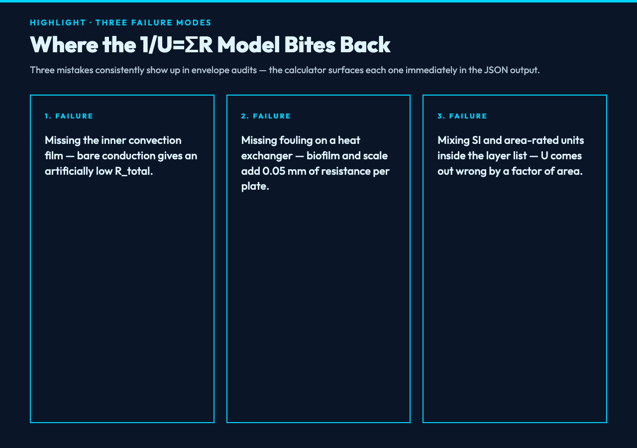
- Forgetting the inner convection film. A bare conduction calculation — one conduction layer, no convection on either side — reports an artificially low R_total and an artificially high U. The film coefficient on the air side is small but non-zero, and on the water side of a heat exchanger it is large enough to dominate. The calculator catches this because the U it returns will be obviously higher than the rated value from the manufacturer.
- Missing fouling on a heat exchanger. After a cooling season, a plate heat exchanger picks up biofilm and mineral scale on the water side. Each 0.05 mm of scale adds roughly 0.0004 m²·K/W of resistance per m² of plate area, which is small in absolute terms but compounds across a ten-plate stack. The calculator’s individual layer list lets you add a fouling layer mid-life and see exactly how much U has degraded since commissioning.
- Mixing SI and area-rated units inside the layer list. The most common mistake is feeding a per-area U-value directly into the resistance list instead of converting it to K/W first. The wall then reports a U that is off by a factor of the area, and the JSON echoes the suspicious value back so the error is visible at a glance.
Five examples the calculator handles cleanly
The tool accepts one resistance per line, accepts positive or negative ΔT, and handles three temperature units. The five cases below cover the bulk of the engineering questions the model is asked.
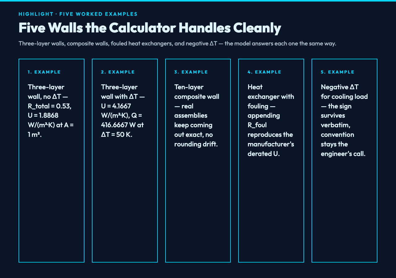
- Three-layer wall, no ΔT. R = [0.02, 0.5, 0.01] K/W at A = 1 m² returns U = 1.8868 W/(m²·K) and skips Q because ΔT was not given. This is the standard envelope-audit shape.
- Three-layer wall with ΔT. R = [0.01, 0.1, 0.01] K/W at A = 2 m², ΔT = 50 K returns U = 4.1667 W/(m²·K) and Q = 416.6667 W. The Q is the heat load that the wall imposes on the upstream system.
- Ten-layer composite wall. Real wall assemblies — gypsum, sheathing, insulation, air gap, brick — often have six to ten layers. The calculator accepts any number of lines; R_total and U still come out exact.
- Heat exchanger with fouling. Adding a fouling resistance R_foul = 0.0004 m²·K/W per plate converted to K/W (divided by plate area) and appended to the layer list reproduces the manufacturer’s derated U.
- Negative ΔT for cooling load. ΔT = -20 K returns a negative Q, which the calculator keeps verbatim — the sign convention is the engineer’s responsibility.
Why the layer order is irrelevant under the area curve
Because the formula is a sum of scalar terms divided by area, the order in which you list the resistances does not affect the result. A wall with an inner convection film, a brick conduction layer, an air-gap conduction layer, a sheathing conduction layer, and an outer convection film returns the same U whether you list convection-first or conduction-first. This is one of the rare cases in heat-transfer work where the audit does not depend on writing the layers in any particular sequence — which is itself useful when the data comes from a spreadsheet built by someone who never had to.
When the flat-wall model is the wrong tool
The flat-wall 1/U = ΣR formula assumes one-dimensional conduction, uniform area, and no internal heat generation. Three classes of problem break that assumption and need a different tool.
- Pipe and tube walls. A cylindrical geometry uses the log-mean radius form, not the flat-wall sum. For those, use a cylindrical resistance calculator or a pipe-insulation sizing tool.
- Two-dimensional conduction with fins. Extended surfaces, finned tubes, and heat sinks need a fin-efficiency correction on top of the U-value. The flat-wall model treats the fin as if it conducted uniformly, which overstates Q.
- Transient or unsteady heat transfer. The model assumes steady state. For start-up, cool-down, or thermal-mass calculations, the time constant and the Biot number matter, and the 1/U = ΣR result is only the boundary condition at t → ∞.
How the calculator handles unit and sign conventions
All resistances are entered in K/W. Temperatures are accepted in K, °C, or °F; a °C difference equals a K difference, a °F difference is converted by ×5/9. ΔT may be positive or negative, and the resulting Q carries the same sign as ΔT. The decimal-places option lets the JSON output be tuned for spec sheets (4 places is the default), pocket calculators (2 places), or full audit logs (6+ places).
Each resistance value is treated as already area-adjusted — a convection resistance is R_conv = 1/(h·A), a conduction resistance is R_cond = d/(k·A), a fouling resistance is R_foul = R_f”/A. The tool does not perform those conversions itself; it accepts the per-area factor as already applied. This is the convention used in ASHRAE Handbook fundamentals and in EN ISO 6946, and it matches the way the values appear on manufacturer datasheets. Run the calculator against a known assembly and the JSON will tell you whether your per-layer convention matches the tool’s before you trust the U.
Verifying a vendor U-value against the calculator
The standard audit pattern is: take the manufacturer’s published U for a wall assembly, divide the inverse into the layer list the datasheet lists, and run those resistances through the calculator. If the calculator’s U matches the datasheet’s U within rounding, the layer list is complete. If the calculator returns a U noticeably higher than the datasheet, a layer is missing — typically the inner convection film or a year-two fouling factor. If the calculator returns a U noticeably lower, a layer is double-counted or a unit conversion is wrong.
This is the same audit loop that catches the most common engineering mistake in envelope work: a wall that “looks right” by U but fails under load because the layer list is incomplete. The flat-wall U-value calculator makes the audit a few-keystroke operation, and the JSON output becomes the receipt you attach to the spec sheet. For a broader view of how the per-area U compares against other thermal quantities, browse the full elysia-tools catalog.
