
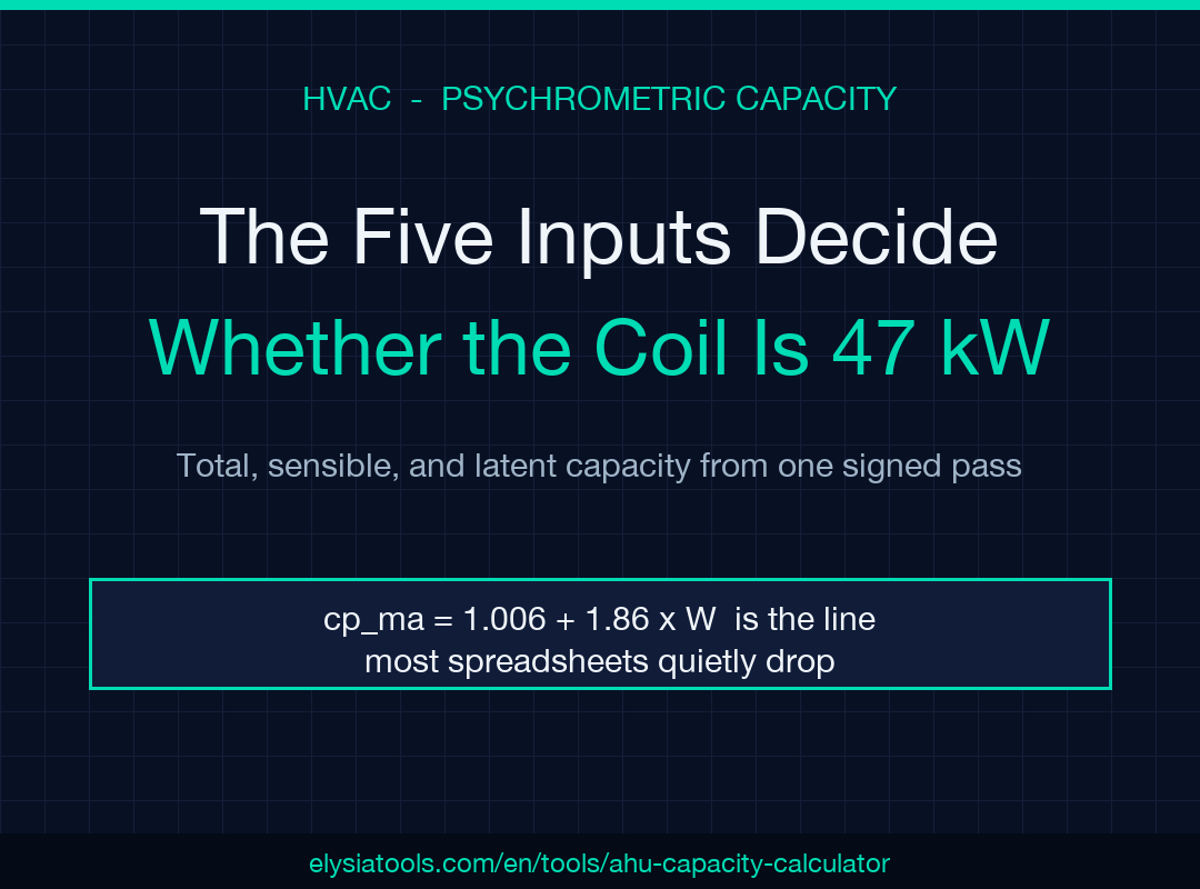
When the entering and leaving air state, the dry-air mass flow, and the Magnus humidity fit are the only things standing between your cooling coil’s nameplate and the answer that lands on the psychrometric chart, you don’t have a sizing problem — you have a state-input problem. Most engineers treat the AHU coil capacity check as a textbook total-load formula and discover, three commissioning rounds in, that their sensible number quietly tracks the cooling coil’s surface temperature while their latent number silently assumes an indoor humidity the building never sees. The AHU Coil Capacity Calculator (Cooling / Heating) collapses the full total / sensible / latent / SHR derivation into a single signed-pass — works for cooling or heating, with W or RH on either side — so the answer you ship is the answer that lands on the coil selector.
The five inputs decide whether your coil is a 33 kW chiller or a 47 kW one
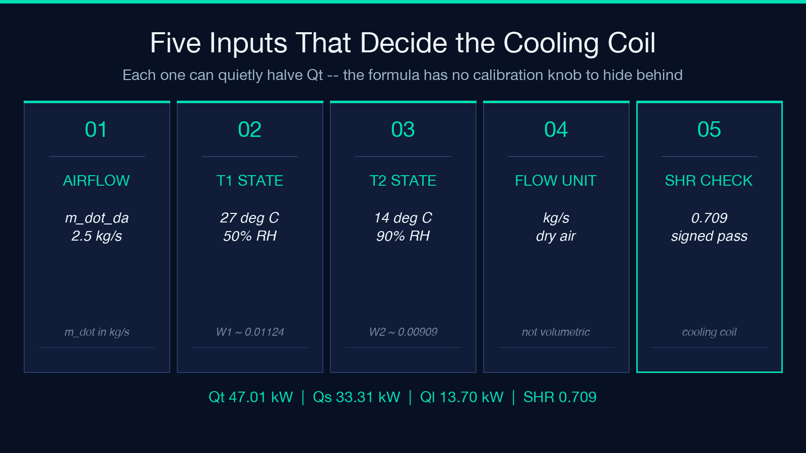
Every coil capacity number in the world is the product of the same five inputs: dry-air mass flow ṁ_da, the entering dry-bulb T1 with its humidity state, the leaving dry-bulb T2 with its humidity state, and the flow unit. Each one of them can quietly halve the result. A 2.5 kg/s flow paired with an indoor humidity the operator thinks is 50% but the controller is logging as 35% produces a 4 kW sensible difference on the cooling side, which is the difference between a coil that meets the nameplate and a coil the field tech has to swap.
The reason the inputs get so much attention is that the formula chain — Qt = ṁ_da·(h1 − h2), Qs = ṁ_da·cp_ma·(T1 − T2), Ql = Qt − Qs, SHR = Qs / Qt — is purely arithmetic once the states are right. There is no calibration coefficient to hide behind. If T1, T2, W1, W2, and ṁ_da are right, the four numbers that come out are right. If any one is wrong, all four are wrong, and the SHR you report to the design team has the wrong shape entirely. The tool picks the right answer every time only when the inputs are honest.
The signed-result design matters for the heating-side workflow. A heating coil without a humidification stage has W1 ≈ W2, which forces Ql to near zero and SHR toward 1.000. A preheat coil with steam injection has W2 > W1, which makes Ql positive and SHR drops. The same formula handles both directions, and the calculator keeps the sign convention consistent whether the air is warming up or cooling down. That single property is what lets the design team use the same selector across the airside schematic.
The Magnus humidity fit is where most field-state inputs go wrong
The humidity ratio W is not a knob the operator measures directly. It is derived from either a relative humidity reading (φ) or a wet-bulb reading (Tw), and the conversion goes through the Magnus saturation fit:
W = 0.622 · P_w / (P_atm − P_w)
with P_w = φ · P_ws(T), and P_ws from the standard ASHRAE Magnus form. The calculator wires this in directly, but the inputs that come in from the BMS rarely match the form the formula expects. A controller reporting “humidity” might mean RH, might mean absolute humidity in g/kg, might mean wet-bulb. Each one gives a different W, and each W gives a different enthalpy, and each enthalpy gives a different Qt.
The cooling-coil example with ṁ = 2.5 kg/s, T1 = 27 °C / RH1 = 50% → T2 = 14 °C / RH2 = 90% makes this concrete. At 27 °C 50%, P_ws(27) ≈ 3.604 kPa, P_w = 1.802 kPa, W1 ≈ 0.01124 kg/kg. At 14 °C 90%, P_ws(14) ≈ 1.613 kPa, P_w ≈ 1.452 kPa, W2 ≈ 0.00909 kg/kg. Enthalpies: h1 = 1.006·27 + 0.01124·(2501 + 1.86·27) = 55.85 kJ/kg da, h2 = 37.04 kJ/kg da. Qt = 2.5·(55.85 − 37.04) = 47.0 kW. The full chain is in the worked example on the calculator page so you can verify the arithmetic by hand if the field reading is in question.
The heater-side example — ṁ = 3 kg/s, T1 = 5 °C / W1 = 3 g/kg → T2 = 30 °C / W2 = 3 g/kg — drives the point home. With W1 = W2 = 0.003, no moisture is added. h1 = 12.58, h2 = 37.85, Qt = 75.80 kW, Qs = 75.87 kW, Ql ≈ 0, SHR ≈ 1.000. The minus-0.07 kW on Ql is the rounding residue of the moisture-correction term, not a defect. If a field reading comes back with non-zero Ql on a heating coil that has no humidification stage, the input state is wrong — usually the BMS is reporting wet-bulb instead of W.
The cp_ma moisture correction is the line most spreadsheets drop
The sensible heat formula Qs = ṁ_da·cp_ma·(T1 − T2) is not a constant-cp calculation. The moist-air specific heat cp_ma depends on the humidity ratio:
cp_ma ≈ 1.006 + 1.86·W [kJ/(kg da·K)]
For the cooling example, W̄ = (0.01124 + 0.00909) / 2 ≈ 0.01017, so cp_ma ≈ 1.0249. The naive constant-cp version uses cp_ma = 1.006 and under-reports Qs by 1.9%. On a 47 kW cooling coil that is a 0.65 kW miss — small in absolute terms but it lands exactly on the threshold between the coil selection that fits and the one that fails to meet the spec sheet on a humidification day. The calculator applies the correction; almost every spreadshheet the field team brings to a submittal review does not.
The moisture-correction line is also what makes the SHR calculation accurate at the edges. SHR = Qs / Qt, with both numerator and denominator derived from the same input state, so any drift in W propagates symmetrically. The 0.709 SHR reported by the cooling example is a real psychrometric property of the coil, not a fitted approximation. If the SHR you get back from the coil selector does not match the SHR from the calculator within 0.01, one of the two has dropped the moisture correction or used a different Magnus form.
What the parser actually does with the humidity input
The calculator accepts W or RH on either side of the coil independently. This matters because real coil states are rarely described symmetrically. The entering side is almost always reported as T + RH (the controller has a humidity probe, not a wet-bulb probe). The leaving side is often a target state expressed as T + W (the design team’s spec sheet says “leave at 9 g/kg”, not “leave at 65% RH”). The parser handles this asymmetry with no special-casing on the user side: feed in whichever humidity form is available for each side, and the conversion happens locally.
For the heating case with W1 = W2 = 3 g/kg, the parser takes both inputs as absolute humidity, computes h1 and h2 directly without going through the Magnus fit, and reports a sensible-only result. For the cooling case with RH1 = 50% and RH2 = 90%, both inputs go through Magnus, but the conversion uses each side’s own T (27 °C and 14 °C) — the same P_ws table, two different lookups, two different W values, two different enthalpy values, and one signed Qt.
The four edge cases that break naive coil selectors
The first edge case is the mixed humidity input (RH on one side, W on the other) where the parser silently does the right thing and the spreadsheet does not. If the field team entered W1 in g/kg but RH2 as a percentage into a manually built calculator, the result is nonsense unless the conversion was explicit. The tool handles it because each input has its own form flag.
The second is the negative SHR when the heating coil is at W2 > W1 (a steam-injection preheat, for example). Ql becomes positive on the heating side and the spreadsheet’s “heating implies sensible-only” shortcut returns a SHR > 1, which is impossible by definition. The signed-result design catches this; the report includes a mode: "heating" field in the metadata so the downstream selector knows to expect latent gain.
The third is the rounding-residue latent on a sensible-only heating coil. Ql is reported as a small negative number (≈ −0.07 kW on the heater example) because the moisture-correction term on the enthalpy derivation is not exactly self-cancelling when W is in g/kg and cp_ma is in kJ/(kg da·K). The audit team should expect this residue and not flag it; if it appears with a magnitude larger than 0.5% of Qt, the inputs are wrong.
The fourth is the signed Qt on a coil that is supposed to be heating only. If a controller logs T1 = 30 °C and T2 = 5 °C (cooler downstream than upstream), the calculator returns negative Qt and the design team should look at the airflow direction before they look at the formula. The tool does not refuse the input; it returns the signed answer and lets the engineer decide whether the coil is correctly piped.
A walk-through: cooling coil sizing for a 47 kW office AHU
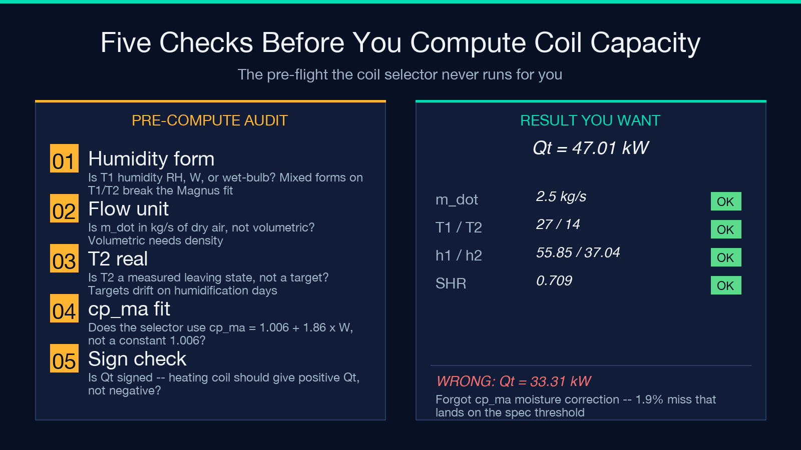
Suppose the design is a 47 kW office AHU with a chilled-water cooling coil. The spec sheet says ṁ_da = 2.5 kg/s, T1 = 27 °C, RH1 = 50%, T2 = 14 °C, RH2 = 90%. The controller has all four. The coil selector manufacturer asks for Qt, Qs, Ql, and SHR before they can match a frame size.
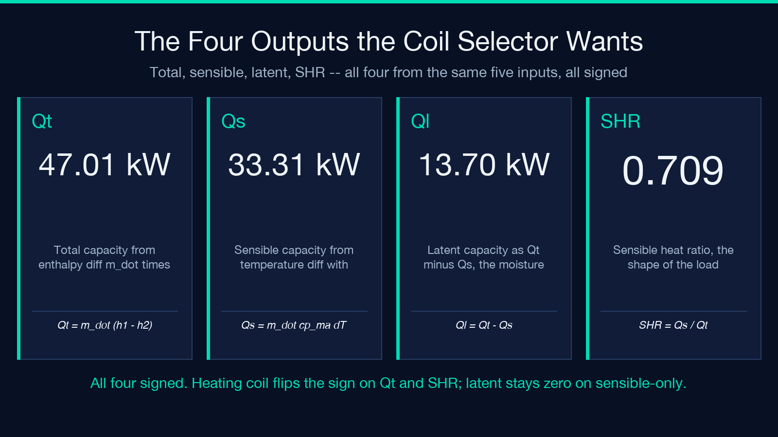
Step one: enter the five inputs into the calculator. The form populates ṁ = 2.5 kg/s, T1 = 27, h1Input = “rh”, h1Value = 50, T2 = 14, h2Input = “rh”, h2Value = 90. Step two: take the four outputs. Qt = 47.01 kW, Qs = 33.31 kW, Ql = 13.7 kW, SHR = 0.709. Step three: send the JSON payload to the coil selector. The selector returns a 4-row coil, which is the frame size the design team already had in mind.
The full worked example — including the Magnus P_ws lookups, the cp_ma correction, and the SHR derivation — is reproduced verbatim in the calculator’s example output so the submittal package has the chain of custody back to the psychrometric reference. Compare against the Psychrometric Properties calculator to verify h, W, and the saturation line independently before the submittal goes to the manufacturer.
How the AHU coil capacity check fits a real design workflow
The psychrometric inputs come from the design load calc, the controller logs the leaving-side state, and the coil selector takes the four derived numbers. The AHU Coil Capacity Calculator sits between them, doing the arithmetic that the spec sheet expects in the exact form the manufacturer wants. It does not replace the load calc; it does not replace the controller; it does not replace the coil selector. It is the bridge.
The cooling load side is handled by Cooling Load Calculator for envelope transmission + infiltration, and the heating load side by Heating Load Calculator. The airside state downstream of the coil is verified against the Dew Point Calculator HVAC to confirm there is no condensation on downstream components, and the compressor lift against Refrigerant Pressure-Temperature Lookup. For the heating side with a chilled-water preheat plus a steam-injection final stage, the sensible/latent split is computed independently with Sensible / Latent Heat Split.
The calculator does not pretend to be a coil selector. It is a sign-and-report tool: hand it five honest inputs, it hands back four honest outputs and a JSON payload that the design package can quote. If the inputs are not honest, no tool in this chain can rescue them. The Magnus fit is documented, the cp_ma correction is documented, the SHR is the ratio of two of the outputs, and the result is signed so the direction of the air-side heat transfer is never ambiguous. For a deeper HVAC systems view, Thermal Comfort PMV-PPD gives the occupied-zone verdict that the AHU serves.
When coil capacity stops being a formula problem
The arithmetic stops being the hard part the moment the inputs are honest. Three things make the inputs dishonest, and none of them is the formula. The first is the humidity-input form: every BMS reports humidity differently, and the formula expects W or RH, not “humidity”. The second is the flow rate: ṁ_da in kg/s requires a clean mass-flow reading, not a volumetric flow converted by a stale density. The third is the air-side state under part-load: a coil selected for 47 kW at design returns Qs = 33.3 kW, but at 60% airflow it returns Qs = 20 kW and SHR rises because the latent term does not scale linearly with airflow. The tool handles all three if you feed it the form it expects; the design team’s job is to make the field data match the form. For the compressor-side view of how the cooling coil’s load changes at part-load, the Condensing / Evaporating Temperature Calculator gives the refrigerant-side verdict.
The closing rule of thumb: if the calculator reports SHR outside 0.3–1.0, the inputs are wrong (humidity form mismatch, flow unit mismatch, or stale T2 from a controller that has not refreshed). If SHR is inside that range but Ql looks suspicious, the moisture-correction term is doing its job and the field reading is real. If Qt is positive when it should be negative (or vice versa), the airflow direction is reversed and the coil is piped wrong, not sized wrong. The tool returns the answer in the form the design team needs; the interpretation is the design team’s job. Try the AHU Coil Capacity Calculator on your next cooling-coil submittal and see whether the nameplate holds.
Explore more tools at elysiatools.com.
