Why Polarizing a Light Wave Is the Simplest Way to Control It
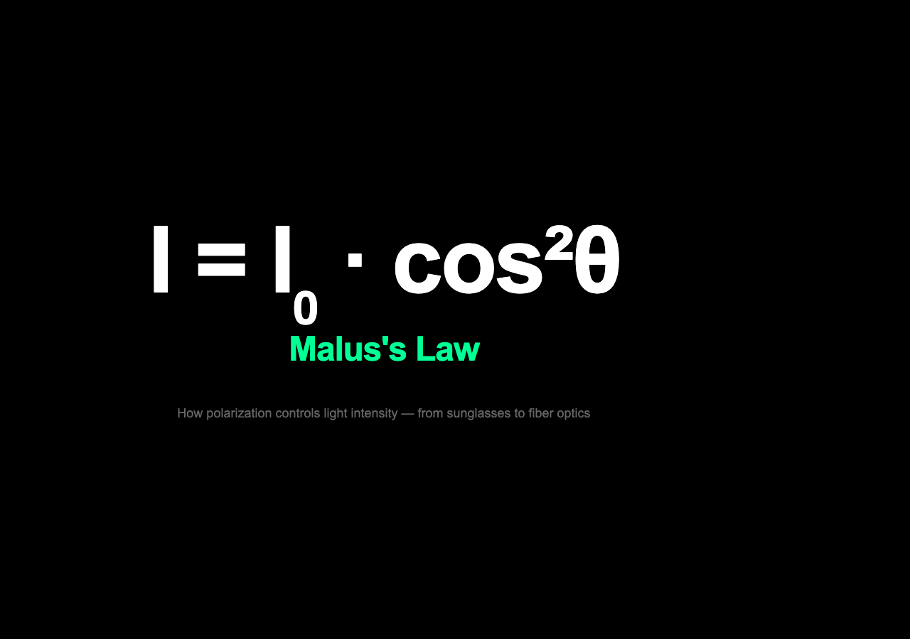
When you rotate a pair of polarizing sunglasses and watch the sky suddenly dim and brighten again, you are watching Malus’s law in real time. The relationship is deceptively simple: I = I₀ · cos²θ. The intensity of light emerging from a polarizer equals the intensity of the incoming light multiplied by the square of the cosine of the angle between the light’s polarization direction and the polarizer’s transmission axis. One equation. A few seconds of observation. And it explains everything from why crossed polarizing filters can block all light to why your phone screen looks dark from an angle.
What Polarization Actually Means
Before Malus’s law makes sense, polarization itself needs a brief explanation. A light wave is an electromagnetic oscillation traveling through space. That oscillation can happen in any direction perpendicular to the travel direction — up, down, left, right, any angle. Unpolarized light, such as sunlight or a light bulb filament, contains waves vibrating in all these directions simultaneously. A polarizing filter is a material with a crystalline structure that only allows light oscillating along one specific axis to pass through. The light that emerges is said to be linearly polarized — all its electric field vectors oscillate in the same plane.
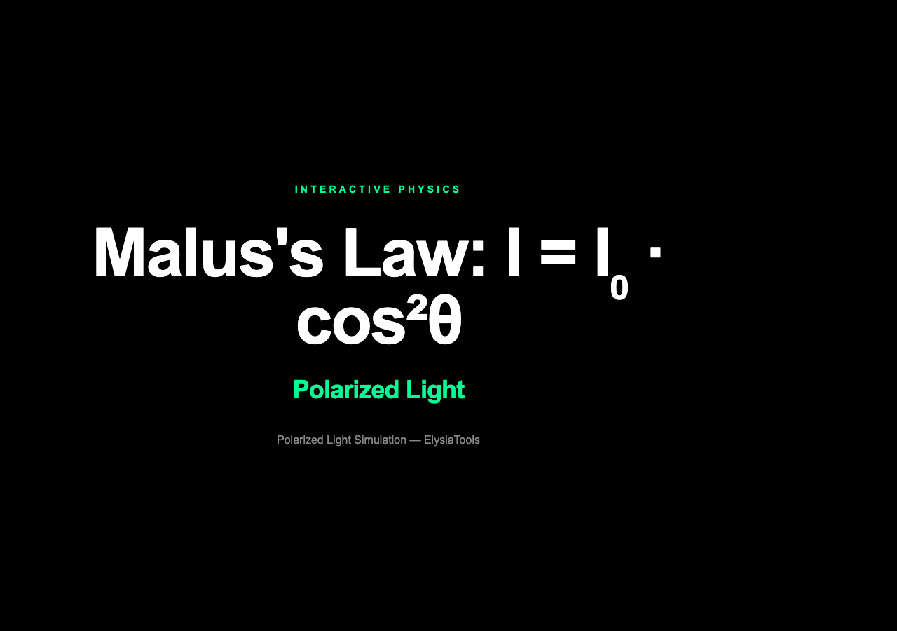
The Polarized Light simulation lets you explore this directly. Start with an unpolarized source and watch the polarizer convert it into a beam with a single, adjustable polarization direction. Adjust the polarizer angle and observe how the transmitted intensity and polarization angle both change. This is the foundation for everything that follows.
Malus’s Law: Intensity and Angle
Once light is polarized, passing it through a second polarizer at an angle θ relative to the first gives you the intensity relationship named after Étienne-Louis Malus, who first described it in 1809. When the two axes are aligned (θ = 0°), all the polarized light passes through — cosine of 0° is 1, so the intensity remains at I₀. When the axes are crossed (θ = 90°), no light passes through — cosine of 90° is 0, and so is the intensity. At 45°, the intensity drops to exactly half of the polarized beam’s original value.
The simulation’s intensity graph plots this relationship in real time. As you rotate the analyzer (the second polarizer), the graph shows a smooth cos² curve. This is not an approximation or a model — it is a direct experimental observation of the electromagnetic wave’s geometry.
Wave Plates: When Light Slows Down in One Direction
Linear polarization is the simple case — the electric field oscillates in a single plane. But what happens when light enters a material that slows one component of the wave more than another? This is exactly what a wave plate does. Made from a birefringent crystal (a material with different refractive indices along different crystal axes), a wave plate delays one polarization component relative to the other.
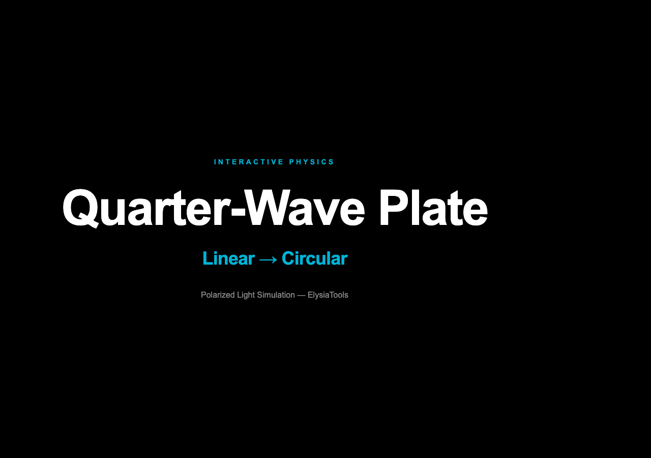
A quarter-wave plate (λ/4) introduces a 90-degree phase retardation between two perpendicular polarization components. A linearly polarized beam entering a quarter-wave plate at 45° to the crystal axes emerges as circularly polarized — the electric field vector rotates as the wave propagates, completing one full rotation per wavelength. Rotate the input polarization angle and you can produce elliptical, circular, or linear output states depending on the geometry.
The simulation’s wave plate panel shows this transformation explicitly. Toggle the wave plate on, set its angle, and watch how the output polarization state changes. The Stokes parameters visualization (S0, S1, S2, S3) gives you a complete picture of the polarization ellipse at each stage.
Why This Matters Beyond the Lab
Polarization is not an academic curiosity. It is the operating principle behind the liquid crystal display on your desk, the 3D movie in a theater, the fiber-optic link carrying your internet traffic, and the sunglass lenses rotating on your face. Every LCD pixel contains a liquid crystal that acts as a voltage-controlled wave plate — applying a small electric field changes the crystal’s orientation, which changes the polarization of the light passing through, which determines whether that subpixel allows light to reach your eye. The display you are reading this on is a polarization machine.

In fiber optics, polarization maintaining fiber is designed to keep the polarization state of a laser beam stable over kilometers of transmission. In remote sensing and atmospheric science, the degree of polarization in scattered sunlight reveals the composition and structure of aerosols and cloud particles. In photography, a polarizing filter darkens skies and eliminates glare from non-metallic surfaces by suppressing reflected polarized light.
All of these applications share the same core physics: Malus’s law governs how intensity varies with polarization angle, and wave plate optics govern how polarization states transform. The simulation lets you build the intuition that ties all of these technologies together.
This is why the same physics that lets you dim a beam with two polarizing filters also powers the liquid crystal display on your wrist, the laser scanner at the grocery checkout, and the 3D movie playing in a theater near you. Malus’s law doesn’t just describe light — it has become the operating principle for an entire technology stack. And you can verify it yourself right now: rotate a polarizing filter in front of a backlit screen and watch the intensity trace on the graph. The equation is clean. The implications are everywhere.