You flip off the bedroom light. The bulb dims over roughly a quarter-second before going dark. You assume the filament is cooling. You’re wrong. The inductor in the circuit — not thermal inertia — is keeping the current alive, like a flywheel that refuses to stop when you cut the power. If you could watch on an oscilloscope, you’d see the current ring down as a decaying oscillation, not a clean step.
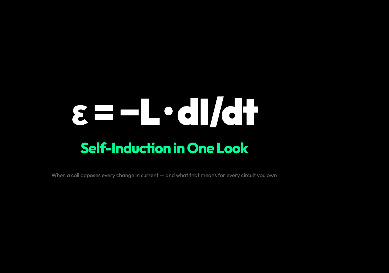
This resistance to change is called self-induction. It arises from one elegant principle: a changing current creates a changing magnetic field, and that field induces a voltage that opposes the change that created it.
The Core Equation
The quantitative description of self-induction is given by Faraday’s law applied to a single coil:
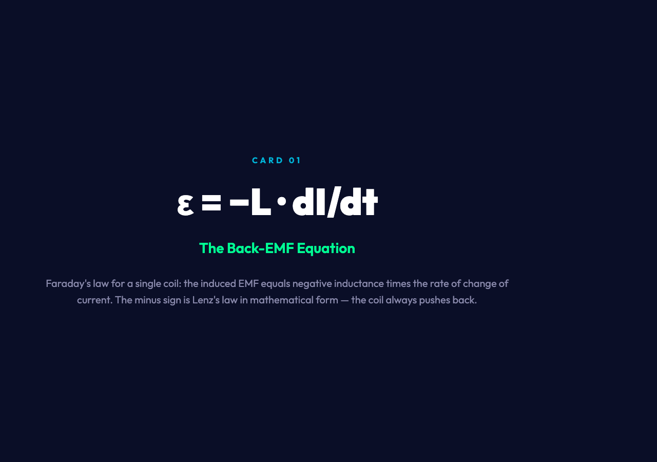
EMF = -L · dI/dt
where: – EMF is the induced voltage (measured in volts, V) – L is the inductance of the coil (measured in henries, H) – dI/dt is the rate of change of current (in amperes per second, A/s) – The minus sign (-) expresses Lenz’s law: the induced EMF always opposes the change that created it
The inductance L depends on the coil’s geometry — number of turns N, cross-sectional area A, length l, and the magnetic permeability μ of the core material:
L = N^2 · mu · A/l
A coil with more turns, a larger area, a shorter length, or a magnetic core (high μ) will have a higher inductance. The default value in the interactive simulation is L = 5.0 H — a fairly large inductor typical of laboratory demonstration apparatus.
Lenz’s Law in Action
The minus sign in the EMF equation deserves special attention. It tells us the induced voltage doesn’t simply appear — it fights back. When current through a coil increases, the induced EMF creates a counter-current that slows the increase. When current decreases, the induced EMF creates a pro-current that tries to maintain the original current.
This is Lenz’s law in action, and it means an inductor doesn’t just dissipate energy like a resistor. It stores energy in its magnetic field during the transient phase, then releases it back when the external source can no longer sustain the current.
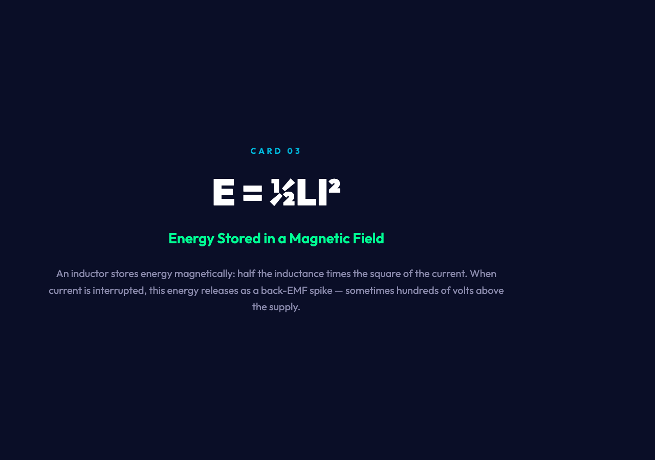
The energy stored in an inductor at a given current I is:
E = 1/2 L I^2
This is magnetic field energy — the same form as kinetic energy (½mv²) but for magnetic fields instead of masses. Just as a massive object rolling down a slope gathers kinetic energy that isn’t easy to shed instantly, a current flowing through an inductor builds up magnetic energy that resists being interrupted.
Growth and Decay: The RL Time Constant
When you connect an inductor to a constant voltage source through a resistor (an RL circuit), the current doesn’t follow Ohm’s law instantly. Instead, it grows exponentially toward its steady-state value:
I(t) = I0 left(1 – e^{-t/ au}right)
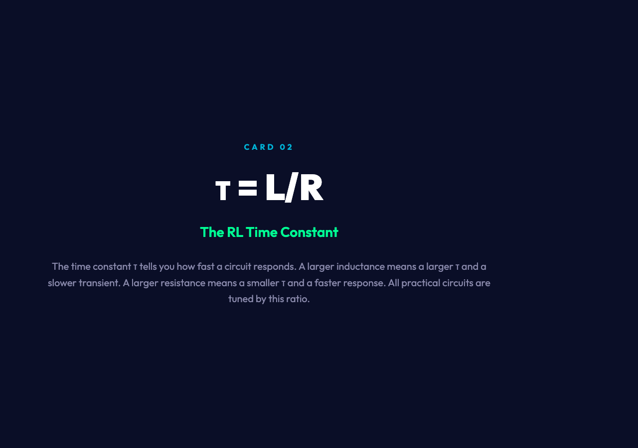
where τ = L/R is the time constant of the circuit — the time required for the current to reach ≈ 63.2% of its final value. When you disconnect the source, the current decays as:
I(t) = I0 e^{-t/ au}
The time constant τ = L/R determines both how quickly the current builds up after a voltage is applied, and how quickly it rings down after the source is removed. A larger inductance L means a larger τ and a slower transient. A larger resistance R means a smaller τ and a faster transient.
This interplay between L and R is everywhere in practical circuits. Every time you turn on a DC motor, the inductor in the windings limits the inrush current. Every time you turn it off, the collapsing magnetic field generates a voltage spike that, if unhandled, can damage switches and semiconductors. This is why you see flyback diodes across relay coils and snubber circuits around motors — they’re all managing the energy that inductors release when current is interrupted.
The Interactive Visualization
The simulation at the top of this page lets you manipulate the core parameters and watch the system respond in real time.
What the visualization shows:
- Circuit diagram — a coil connected to a voltage source through a switch
- Current vs. time graph — showing the exponential growth on connection and decay on disconnection
- EMF vs. time graph — showing the back-EMF pulse as the switch is thrown
- Magnetic field lines — animating through the coil, growing when current is increasing and collapsing when it decreases
Try setting the inductance to a large value and throwing the switch. Notice how the current takes longer to reach its steady state. Now set L to a small value and repeat. The transient becomes nearly instantaneous.
Pay attention to the back-EMF pulse in the EMF graph when the switch opens. That sharp spike — often hundreds of volts above the supply — is the inductor’s stored magnetic energy being released all at once. It’s the same phenomenon that makes old-style fluorescent lights buzz and click when you turn them off, and that requires special protection circuits in DC motor drives.
Why Self-Induction Matters
Self-induction is everywhere once you know what to look for.
Inductors in power supply filters — every DC power supply uses inductors to smooth out voltage ripples. The inductor resists changes in current, filtering the jagged output of rectifiers into something closer to a steady DC voltage.
Ignition systems — the old automotive ignition coil stores energy in a high-inductance primary winding, then interrupts the current abruptly to generate the thousands-of-volts needed to fire the spark plugs. The back-EMF spike is the feature, not the bug.
Gradient coils in MRI machines — these are specialized high-speed inductors that generate the spatially-varying magnetic fields used to encode spatial information in MRI scans. Their self-induction properties determine how fast the gradient fields can be switched — a critical performance parameter for imaging speed.
Cruts and solenoids — the relays and solenoid valves that switch everything from railway signals to industrial process valves are fundamentally inductor-based devices. Understanding their self-induction is essential for designing reliable control electronics.
The humble coil of wire — whether it’s a few turns around a screw or thousands of turns on a laminated iron core — is doing something remarkable: it is measuring the rate of change of current through itself, and actively opposing any deviation from the status quo. It is the closest thing to a mechanical flywheel that circuit theory offers, and its behavior underpins everything from audio crossover networks to particle accelerator beam control.
The next time you flip a light switch, pause for that quarter-second. What you perceive as a slight delay is actually the inductor at work — storing energy in its magnetic field, then releasing it back as the field collapses. Every coil in every circuit does the same thing quietly, thousands of times a second, in power supplies and car ignitions and MRI machines. Understanding self-induction is the first step toward understanding every oscillating system in physics.