
Two numbers in, two numbers out. Every DC and AC circuit problem you’ve ever solved reduces to the same four variables — voltage, current, resistance, and power — and the same two equations. Give any two of them and the other two fall out algebraically. The Ohm’s Law and Power Triangle Calculator keeps the algebra honest, renders the two mnemonic triangles, switches between DC and AC, and reports values in engineering SI prefixes so you stop re-counting zeros. This field guide walks through the equations, the triangles, the AC power-factor correction, the unit gotchas (mA vs µA vs kΩ), and three concrete worked examples. Open the calculator, work each example by hand once, then use the tool as your second pair of eyes when a real schematic lands on your desk.
What Ohm’s Law Actually Says
A resistor, a length of wire, a heating element — every ohmic component obeys the same linear relationship: the voltage across it equals the current through it times its resistance. Symbolically, V = I·R. That single equation has two rearrangements you’ll reach for constantly: I = V/R and R = V/I. Cover the unknown on a triangle and the remaining two reveal how they combine. Voltage is in volts (V), current in amperes (A), resistance in ohms (Ω).
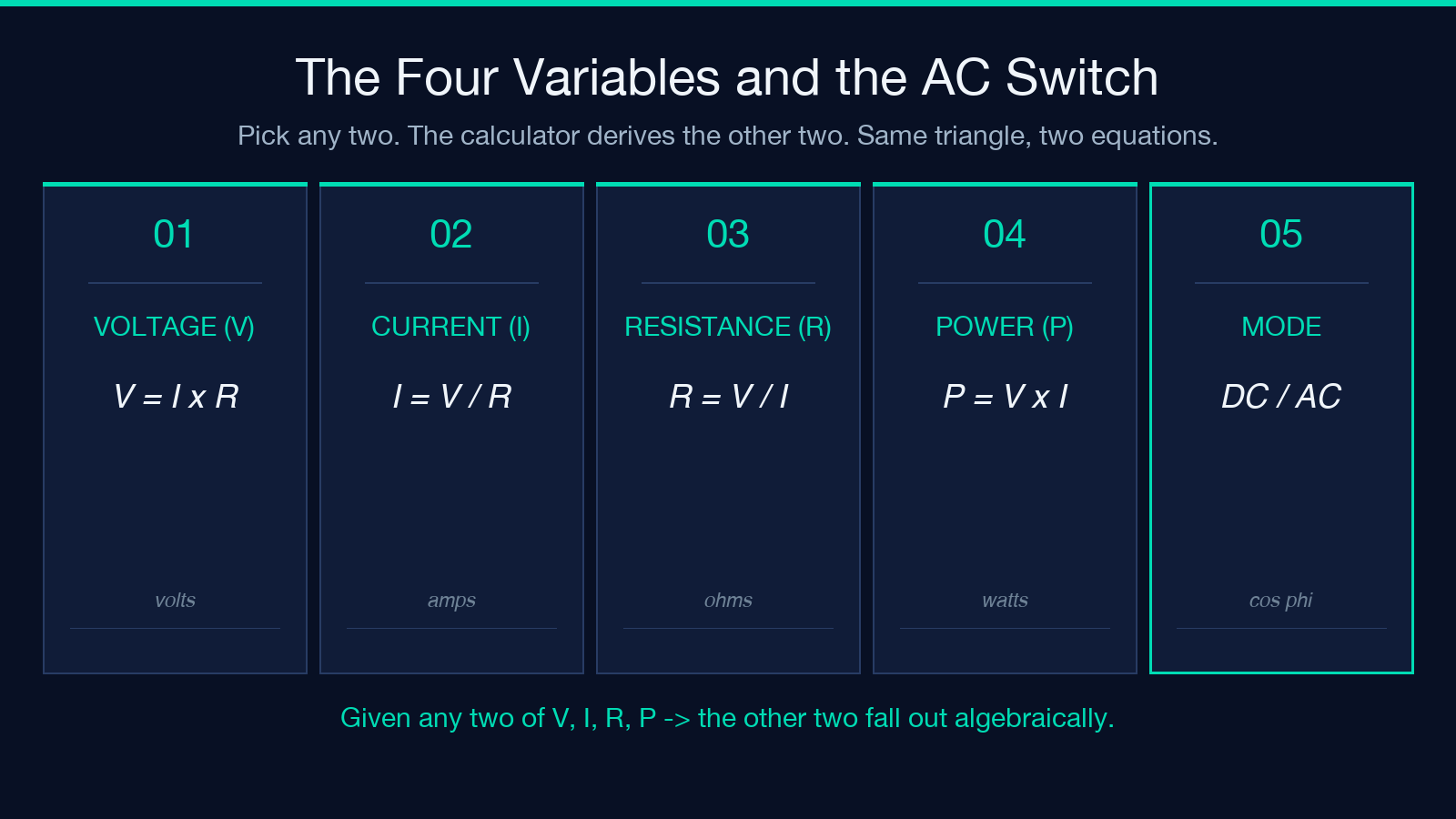
The catch is that Ohm’s law doesn’t say anything about power. For that you need the second equation: P = V·I. Combined with Ohm’s law it gives two more useful forms: P = I²·R and P = V²/R. Power is in watts (W). Three of the four unknowns — V, I, R, P — are linked by Ohm’s law; the fourth is linked to the first three by the power equation. Given any two, the other two fall out. That’s the whole game.
Reading the Two Mnemonic Triangles
The calculator renders two triangles side by side because the equations share variables and the triangles share a visual trick: cover the unknown, the remaining two either multiply (top of triangle) or divide (bottom). The Ohm’s law triangle puts V on top with I × R underneath. The power triangle puts P on top with I × V underneath. To find current from voltage and power, look at the power triangle, cover I — V is next to P, so I = P/V. To find resistance from voltage and power, drop down to Ohm’s law after computing I — R = V/I. The triangles aren’t decoration; they’re a calculator you carry in your head.
The Unit Trap: Why mA and kΩ Exist
A 5 V microcontroller pin driving a 2.2 kΩ pull-up resistor gives you 2.27 mA, not 2.27 A. The raw numbers are correct (I = 5 / 2200), but the answer is meaningless without prefixes. The calculator handles engineering SI prefixes — kΩ (kilo-ohms, 10³), MΩ (mega, 10⁶), mA (milli, 10⁻³), µA (micro, 10⁻⁶), nA (nano, 10⁻⁹). It displays both the human-friendly form (2.27 mA) and the raw numeric (0.00227 A). When you’re sizing a fuse, designing a current-sense shunt, or selecting a wire gauge, the prefix you choose determines whether you look competent or careless. Keep both forms visible — the prefix for your bench, the raw number for your spreadsheet.

DC Worked Example: A Resistor and a Battery
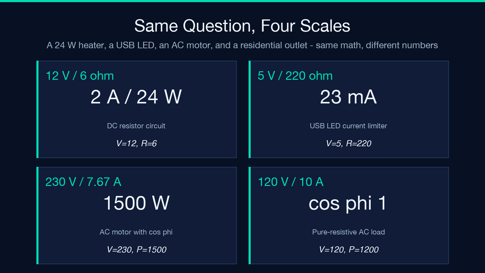
You have a 12 V battery and a 6 Ω resistor. What’s the current and the power dissipated? Apply Ohm’s law: I = V/R = 12 / 6 = 2 A. Then power: P = V·I = 12 · 2 = 24 W. Or directly: P = V²/R = 144 / 6 = 24 W. Same answer, two paths. Now reverse it — you have a 24 W heater running off 12 V. What resistor value does it look like? R = V²/P = 144 / 24 = 6 Ω. The triangle gives you the rearrangement without the algebra. The Ohm’s Law and Power Triangle Calculator shows both the numeric answer and the triangle, so you can verify the rearrangement you used by covering the unknown on the triangle and confirming the remaining two combine the same way.
AC Mode: When Voltage and Current Aren’t in Phase
DC is simple: V and I peak together, P = V·I is the real power delivered to the load. AC isn’t. Motors, transformers, fluorescent ballasts, switch-mode power supplies — every reactive load shifts current out of phase with voltage by some angle φ. The real power becomes P = V·I·cos φ, where cos φ is the power factor (0 to 1). A perfect resistor has cos φ = 1. A purely inductive load has cos φ = 0 (no real power, just energy sloshing back and forth). Most motors run at cos φ = 0.80–0.90. The product V·I is still the apparent power S, measured in VA (volt-amperes), used to size wiring and breakers. The difference between S and P is reactive power Q, measured in VAR. Toggle the calculator into AC mode, set cos φ, and the report shows P, S, and Q separately.
AC Worked Example: Sizing a Motor Circuit
You need to specify the breaker for a 1500 W industrial motor on 230 V AC at cos φ = 0.85. The naive answer — I = P/V = 1500 / 230 = 6.52 A — undersizes the wiring because it ignores the power factor. The correct approach: apparent power S = P / cos φ = 1500 / 0.85 = 1764.7 VA, then I = S / V = 1764.7 / 230 = 7.67 A. That’s 17% more current than the naive calculation. Pick a 10 A breaker, not an 8 A one. The calculator reports both P and S when you set the mode to AC and supply a non-unity power factor, so you can size the wiring correctly the first time. Skip the calculation and you explain to the plant engineer why the breaker trips every time the motor starts under load.
When You Don’t Have a Pure Resistor
Real loads aren’t pure resistors. A diode drops ~0.7 V regardless of current. An LED needs a current-limiting resistor. A battery has internal resistance that varies with state of charge. A capacitor at DC is open-circuit; at AC it’s a reactance Xc = 1/(2πfC). An inductor is the mirror — short at DC, impedance XL = 2πfL at AC. For these, Ohm’s law generalizes to V = I·Z where Z is impedance (resistance + reactance, complex). The calculator focuses on the four pure-resistor variables because that’s the 90% case. When you need reactance, impedance, or phasor math, layer the resistor-color-code decoder alongside it — but for the daily grind of LED current-limiters, voltage dividers, fuse sizing, and motor circuits, the four variables are enough.
Closing the Loop: Build the Habit
Pull the calculator up once a week and run a circuit you’re working on through it. Given voltage and resistance, derive current and power by hand first, then confirm with the tool. Switch to AC, set a power factor you’ve never tried, and watch the apparent-power number jump. The triangle visualizations aren’t a learning aid — they’re the actual mental model engineers use in their head when they sketch a circuit. Build that mental model deliberately and you’ll never have to Google “V=IR which side is which” again. The four-variable triangle trick transfers to capacitor charge (Q = C·V), inductor voltage (V = L·dI/dt), and Ohm’s law for fluids (ΔP = Q·R). Same shape, same cover-the-unknown trick. Once you see it once, you see it everywhere.
Explore more tools at elysiatools.com.
