
Sensible capacity is the dry-bulb work; latent capacity is the humidity tax. When an air-handling-unit coil runs cold, the air loses both temperature and water — and the same formula that captures the cooling case returns a negative total if you swap which side you call “entering”. That single sign convention is the source of most AHU capacity mistakes, and a careful AHU Coil Capacity Calculator does three things in one pass: it derives humidity ratio from either relative humidity or directly supplied W, computes sensible and latent components independently, and reports a signed total that is negative for cooling and positive for heating. This field guide walks through the inputs and the arithmetic that gives you those numbers — see Elysia Tools for a working calculator, and pair it with a psychrometric chart for sanity-checking.
How the calculator reads the air state from two numbers
The AHU coil model needs two air states — entering and leaving — each described by a dry-bulb temperature plus one humidity input. The humidity input is a choice: either relative humidity φ (a percentage) or humidity ratio W (kg water per kg dry air). When you pick φ, the calculator runs the Magnus saturation fit to convert φ into W; when you pick W, the value is taken as-is. Enthalpy h is then computed for each state using h = 1.006·T + W·(2501 + 1.86·T) [kJ/kg da], and the sign of (h_entering − h_leaving) decides whether you have a cooling coil or a heating coil.
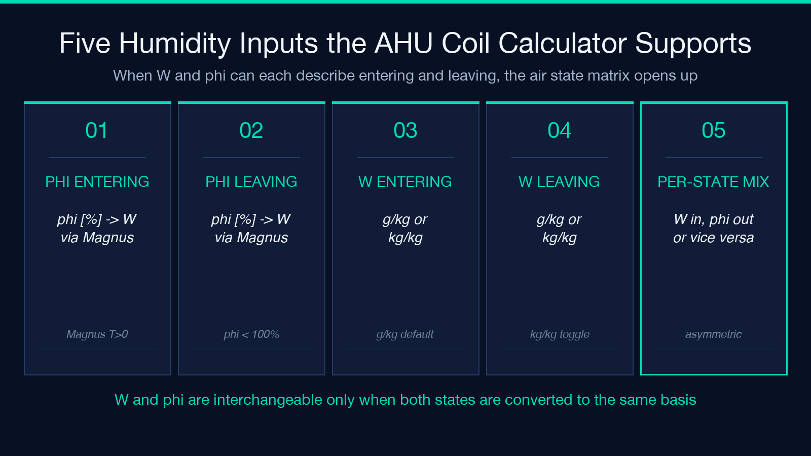
- Mode φ (default): supply φ in percent. The calculator derives W via Magnus at the local T.
- Mode W: supply W directly in g/kg or kg/kg. Use this when you already have a psychrometric measurement.
- Per-state mode: entering and leaving can use different modes — common when one side comes from a wet-bulb measurement and the other from a chilled-air sensor.
For a worked example, try the AHU Coil Capacity Calculator with ṁ = 2.5 kg/s, T1 = 27 °C, φ1 = 50%, T2 = 14 °C, φ2 = 90% — the calculator returns Qt = 47.0 kW, Qs = 33.31 kW, Ql = 13.69 kW, SHR = 0.709.
Why humidity mode is the load-or-stall moment
If your humidity value comes from a relative-humidity probe, the calculator converts to W before it computes enthalpy; if your humidity value comes from a dew-point or psychrometric chart, you already have W. The two paths converge to the same h when the inputs are correct, but a single-digit slip — φ = 50 entered as 5, or W = 0.011 entered as 0.11 — silently changes Qs by a factor of 10. Three rules of thumb keep the sign clean:
- Cooling: h_entering > h_leaving → Qt positive, sensible + latent both positive.
- Heating: h_entering < h_leaving → Qt positive (the calculator flips the sign for you), Ql is zero or near-zero when W1 = W2.
- Cooling with reheat: sensible fraction is defined by SHR = Qs/Qt, but Qt is still the net enthalpy change — reheat stages add their own Qt.
The four numbers behind every coil capacity: Qt, Qs, Ql, SHR
A coil capacity report is four numbers, and each one answers a different question. Qt is the total energy the coil must move (or add) — the figure your chilled-water plant sizing depends on. Qs is the part that goes into the temperature change; Ql is the part that goes into condensing water out of the air. SHR = Qs/Qt is the ratio an engineer reads first to know whether the coil is mostly a sensible or mostly a latent machine. Cooling coils for comfort applications usually land at SHR between 0.6 and 0.85; dehumidification coils run lower.
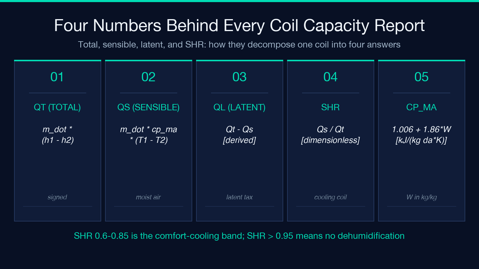
- Qt = ṁ_da · (h1 − h2) — total coil load, signed.
- Qs = ṁ_da · cp_ma · (T1 − T2) — sensible component, where cp_ma ≈ 1.006 + 1.86·W [kJ/(kg da·K)].
- Ql = Qt − Qs — latent component, derived.
- SHR = Qs / Qt — sensible heat ratio, dimensionless.
For cooling-coil sizing where you know the desired leaving condition, the AHU Coil Capacity Calculator lets you fix T2 and φ2 and back-calculate Qt. For heating-coil runs (pre-heat coils in cold climates, reheat in VAV systems) the same calculator accepts W1 = W2 as a short-circuit input to suppress the latent term.
Three humidity edge cases that break the formula
The Magnus saturation fit works for “normal” indoor and outdoor conditions, but three common cases produce numbers that look reasonable but are quietly wrong. Knowing the edge cases is how you catch them before they reach a plant-room printout.
- Below 0 °C: the Magnus fit is calibrated for T > 0; subzero entering air with a saturated leaving side produces W values that diverge from ASHRAE Fundamentals. Use a measured W directly when T1 < 0.
- φ > 100%: if your humidity sensor reports 102% during a fog event, the formula accepts the value and produces a W above saturation. Clamp φ to 100 before computing.
- W in g/kg vs kg/kg: the calculator handles both with a unit toggle, but if you paste a value from a psychrometric chart without checking the axis label, you can be off by 1000×.
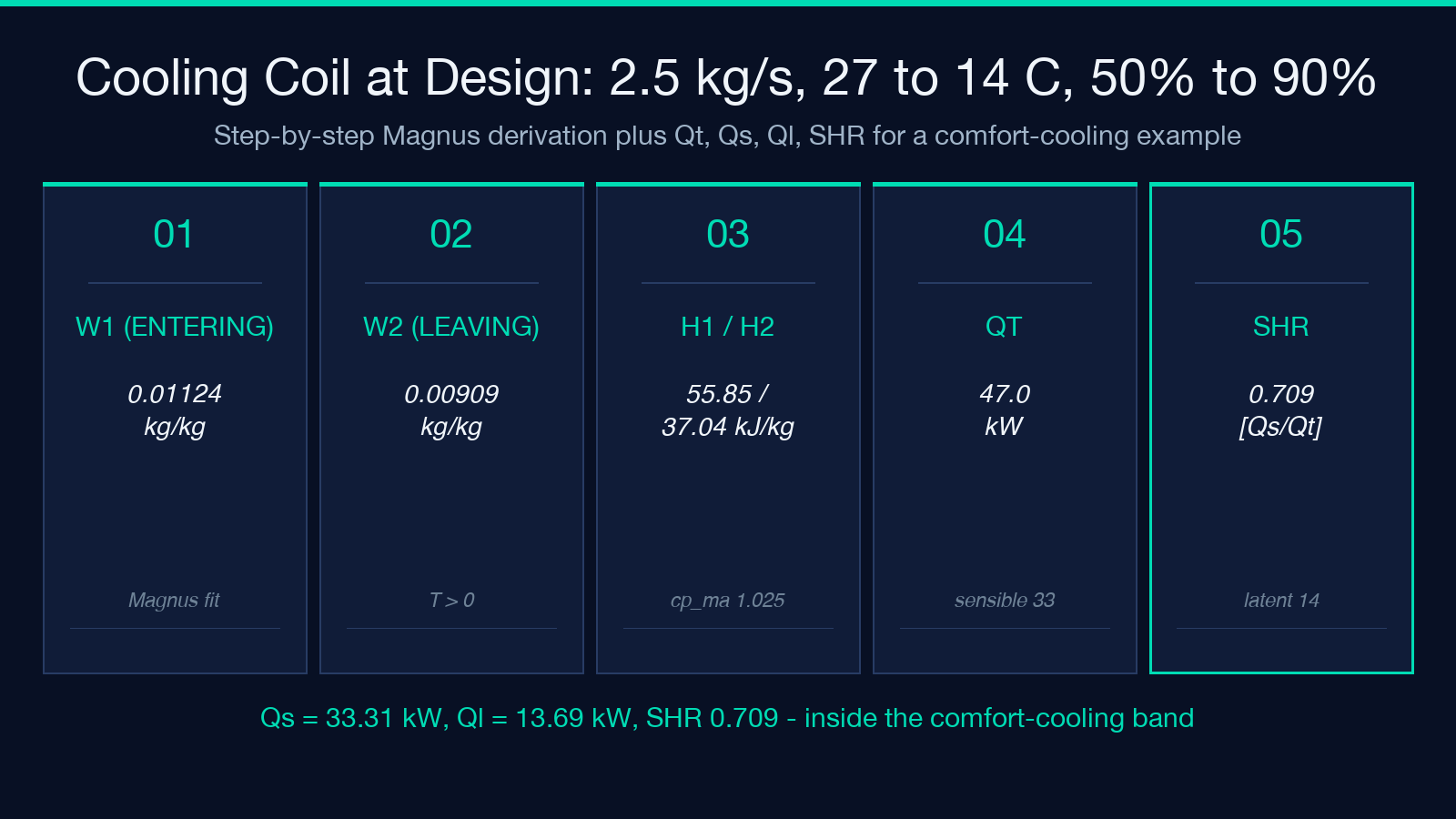
For the worked example referenced earlier, the Magnus-derived values are W1 = 0.01124 kg/kg and W2 = 0.00909 kg/kg — both inside the comfort range and well below the saturation curve.
How cp_ma quietly shifts sensible capacity by 1 to 4 percent
The sensible heat formula uses cp_ma — the moist-air specific heat — not the dry-air value 1.006. The moist-air form is cp_ma ≈ 1.006 + 1.86·W. For very dry air (W ≈ 0.005) the correction is small; for humid return air (W ≈ 0.018) it adds about 3 percent. A common shortcut is to use cp = 1.005 throughout and call it “close enough” — the calculator reports the moist-air value so the comparison is honest. When you swap cp = 1.006 into a 50 kW coil, you change Qs by roughly 1.5 kW, which is meaningful at the third significant figure.
Worked example: a chilled-water cooling coil at design conditions
Picture a 2.5 kg/s supply-air stream that enters the cooling coil at 27 °C and 50% RH and leaves at 14 °C and 90% RH. The two humidity ratios (Magnus-derived) are W1 = 0.01124 and W2 = 0.00909 kg/kg. Enthalpies: h1 = 1.006·27 + 0.01124·(2501 + 1.86·27) = 55.85 kJ/kg da; h2 = 1.006·14 + 0.00909·(2501 + 1.86·14) = 37.04 kJ/kg da. Total Qt = 2.5·(55.85 − 37.04) = 47.0 kW. With cp_ma = 1.006 + 1.86·0.01017 = 1.0249, Qs = 2.5·1.0249·(27 − 14) = 33.31 kW, Ql = 47.0 − 33.31 = 13.69 kW, SHR = 0.709. The SHR is inside the comfort-cooling band; the latent load is significant but not dominant. Try the AHU Coil Capacity Calculator to reproduce the numbers, and see the parallel heating-coil case where W1 = W2 = 3 g/kg and SHR climbs near 1.
Pre-cooling coil: when SHR > 0.95 and the latent term rounds to zero
A cooling coil that operates above its dew point only removes sensible heat. The signature is SHR > 0.95, Ql ≈ 0 kW after rounding, and the W values for entering and leaving states that are equal within sensor noise. Three real-world cases produce this profile:
- Economizer mode: outdoor air is cool but dry; the cooling coil runs to lower T but does not condense water.
- Pre-heat reheat staging: a heating coil and a cooling coil in series can produce a SHR that hovers near 1 even though Qt is meaningful.
- Winter cooling in cold climates: entering air is already cold; only sensible trim is needed.
In each case the calculator still reports Qt correctly, but Ql shows as 0.00 kW and SHR rounds to 1.000. That is a legitimate answer, not a defect — if you need a non-zero Ql for a downstream moisture-balance calculation, lower the leaving-side φ or raise the entering-side φ so the air actually crosses the dew point inside the coil.
When the calculator answers “0 kW” — and what to check
A Qt that reads zero or near-zero is almost always a sign-convention artifact, not a real coil. Three things to check, in order:
- Are you in the right mode? φ and W inputs are not interchangeable when one is the “leaving” side. Entering T with leaving W (or vice versa) gives a meaningless h difference.
- Are T1 and T2 in the right order? Cooling expects T1 > T2; heating expects T1 < T2. A swapped pair gives Qt of the wrong sign, which the calculator reports but you may have ignored.
- Is W1 in the unit you think? 0.011 kg/kg and 0.011 g/kg differ by 1000×. The calculator has a g/kg toggle that defaults to g/kg for direct humidity-ratio input.
For more on psychrometric input handling, the Psychrometric Properties calculator on Elysia Tools is the natural next stop after the coil calculator — it lets you back out W, h, and φ from any two of the four state variables. Pair it with the Dew Point Calculator (Magnus) when you need to know whether the air state you described actually crosses the coil’s dew point. For a one-shot breakdown of just the sensible/latent split, the Sensible / Latent Heat Split calculator takes a Qt and Qs and returns SHR (and vice versa) without re-deriving the air state. Explore more calculators at elysiatools.com/en/tools — the AHU coil calculator, psychrometric properties, dew point, and SHR split together cover the full sensible-cooling-plus-dehumidification workflow.
