
I spent a Saturday re-planning a flat’s Wi-Fi with a spreadsheet, and it kept telling me that channel 1 was the problem. The strongest access point in the building sat on it at -42 dBm, forty megahertz wide. But when I finally wrote the footprint down as a range instead of a number, 2402 to 2442 MHz, the fix stopped being a mystery. It was channel 11, which is not even adjacent.
The channel number encodes a center, and nothing else
Wi-Fi channel numbers are not identifiers. Each one marks a center frequency in 5 MHz steps, and that step size is the only thing the number shows you. On 2.4 GHz the center is 2407 + 5n megahertz, so channel 1 lands at 2412 and channel 6 at 2437. On 5 GHz the rule is 5000 + 5n, which puts channel 36 at 5180. On 6 GHz it is 5950 + 5n, with one exception: channel 2 sits at 5935, because the band edge is not a multiple of five.
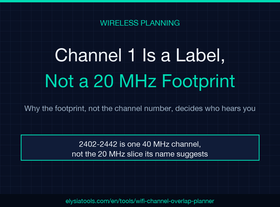
Width is a separate decision, and the width matters more than the number. A 20 MHz channel on channel 1 covers 2402 to 2422 MHz. Widen the same primary channel to 40 MHz and the radio does not grow to the right only. It recenters on 2422 and fills 2402 to 2442. That single number, 2442, is where most 2.4 GHz plans start to fail.
Eleven listed channels, three clean plans
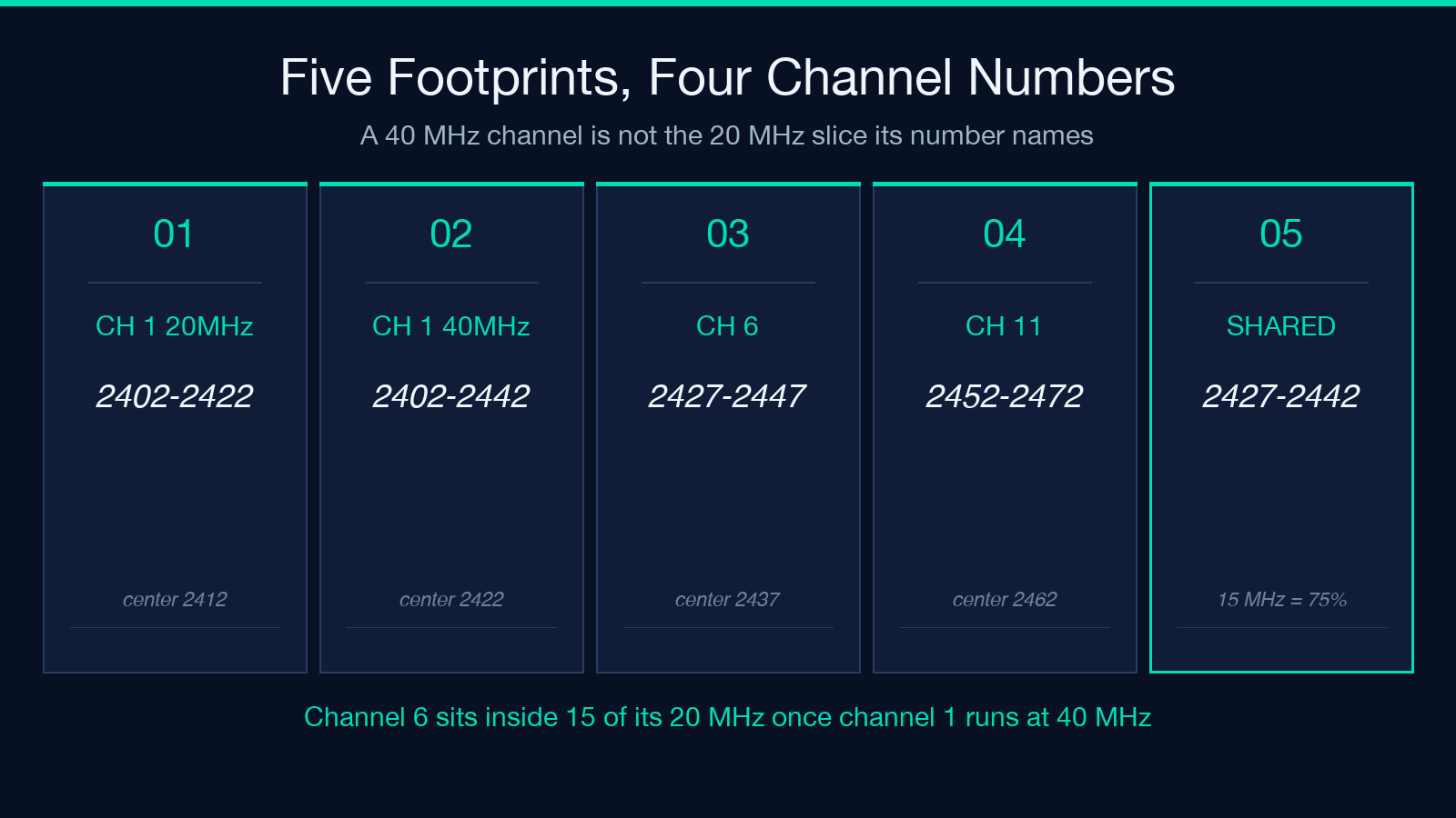
Each 2.4 GHz channel is 5 MHz from its neighbor, and each one is 20 MHz wide. Do the arithmetic and the overlap shows up immediately: channel 1 and channel 2 share 15 of their 20 MHz. So “1, 2, 3” is not a plan, it is one plan written three times.
Only channels 1, 6 and 11 sit 25 MHz apart, so only those three run at 20 MHz without touching each other. The United States exposes channels 1 through 11. Europe exposes 1 through 13, which opens a fourth option at 20 MHz each: 1, 5, 9, 13.
That fourth option is worth flagging as a real gap, because the planner I used never proposes it. Its 2.4 GHz candidate list is fixed to 1, 6 and 11 in both regions. On a European network where channel 11 is congested, the tool still recommends 11 and leaves 5 and 9 unconsidered. Fixing that means scoring all thirteen channels, not three of them. The recommendation is safe, not optimal, and those are different words.
A 40 MHz AP on channel 1 is centered on 2422
Here is a five-access-point snapshot from a flat I planned, entered one per line as name, band, channel, width and RSSI. The strongest transmitter in the building is the one on channel 1, and it is running at 40 MHz:
- Living room, 2.4 GHz, channel 1, 40 MHz, -42 dBm
- Office, 2.4 GHz, channel 6, 20 MHz, -58 dBm
- Main 5G, 5 GHz, channel 100, 80 MHz, -55 dBm
- Studio 6G, 6 GHz, channel 5, 80 MHz, -38 dBm
- Guest 6G, 6 GHz, channel 37, 20 MHz, -76 dBm
Converting each row to a frequency interval shows the real picture: the living room covers 2402-2442, the office covers 2427-2447, and the observed overlap is 15 MHz. That is 75 percent of the office channel, measured against the narrower of the two. The office access point is not on a different channel from the living room one. It is sitting inside 15 of its 20 megahertz. Narrow the living room from 40 MHz to 20 MHz and the shared slice drops to zero.
The weighting is the part worth arguing about
Strong signal should count more than weak signal, and this planner converts dBm into a linear weight with 10^((rssi + 95) / 20). At -95 dBm the weight is 1. At -75 it is 10. At -55 it is 100. Add 20 dB to any observation and you increase its influence tenfold.
For example, the living room at -42 dBm weighs 446.7 and the office at -58 dBm weighs 70.8. Sixteen decibels of difference turns into a 6.3x difference in blame, which is why the office barely registers. Each candidate channel then scores 100 minus 8 times the summed overlap load, and the floor forces the minimum to zero.
The results on this input are blunt:
- Channel 1: load 446.68, score 0
- Channel 6: load 405.81, score 0
- Channel 11: load 0.00, score 100
Two of the three candidates clamp to zero, which cuts the visible difference between them to nothing. That floor is a limit of the scoring, not a measurement of two equally bad channels. According to the planner’s own bundled smoke test, channel 11 wins this input with a score of 100, which matches what the intervals give me by hand. On a dense floor plate, read the load numbers and not only the score, because anything above roughly 12.5 load flattens to the same zero.
Bonding stops at the band edge
5 GHz is where hand plans break, because bonded groups cannot cross a source band boundary. The tool works from four bands: 36-64, 100-144, 149-161 and 165 on its own. An 80 MHz channel needs four contiguous channels from one band; a 160 MHz channel needs eight.
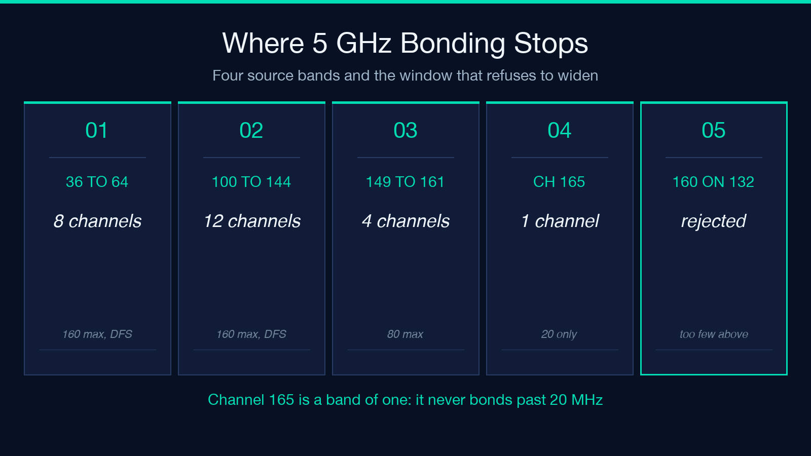
Channel 165 is a band of one, so 40, 80 and 160 MHz are all rejected with the message that channel 165 cannot form a bonded group. That is correct behavior and a common surprise: the highest 5 GHz channel is a 20 MHz island. The 149-161 band holds exactly four channels, so it supports one 80 MHz channel and never a 160 MHz one.
The 12-channel band has a subtler limit. A 160 MHz channel fits at the bottom, 100 through 128, which spans 5490 to 5650 MHz. It does not fit at the top: channel 132 and channel 144 both raise an error, because only four channels remain above them. The widest channels are not available everywhere the band looks wide enough.
80 MHz on channel 36 ends at exactly 5250 MHz
The first 5 GHz group, 36 through 48, spans 5170 to 5250 at 80 MHz. The DFS range starts at 5250, where channel 52’s own 80 MHz slice begins and runs to 5330. There is no guard band between them: the non-DFS slice stops on the first hertz of the radar-protected band.
So an 80 MHz channel on 36 is not flagged DFS, and an 80 MHz channel on 52 is. Widen channel 36 to 160 MHz and the slice runs 5170 to 5330, which crosses 5250 and does get flagged. The planner charges 25 points for the DFS channels 52 through 144, which forces clean channels 149, 153, 157, 161 and 165 above clean channel 100. It also warns that DFS channels may pause or move when radar is detected. The radar case matters most in a coastal region with weather radar inland from the site. That penalty is a stake in the ground: 25 points outweighs a little measured overlap, and on a quiet site you may prefer the DFS channel anyway.
In 6 GHz, fifteen channels are preferred scanning channels
6 GHz channels run 1, 5, 9 and up to 233, giving 59 channels of 20 MHz. The preferred scanning channels are those where the channel number minus 5 is divisible by 16, and there are exactly fifteen: 5, 21, 37, 53, 69, 85, 101, 117, 133, 149, 165, 181, 197, 213 and 229.
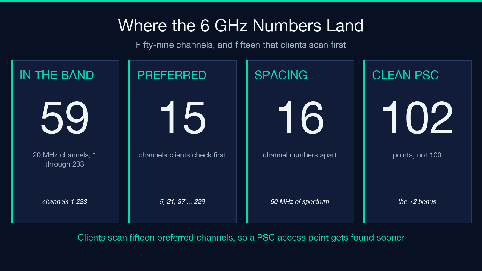
The reason is how clients find an access point. Clients scan the PSC list, not the whole band, so a non-PSC access point is found more slowly even when it is quiet. The planner adds two points for a PSC candidate, which creates a slightly strange maximum: a clean PSC channel scores 102, not 100. For the input above, the planner reported 229, 213, 197, 181 and 165 at 102.00 with zero measured overlap. The studio access point on channel 5 scored zero, because its own 80 MHz slice covers 5945 to 6025 and overlaps itself.
Where the planner stops
I trust the intervals and the bonding rules, and I do not fully trust the ranking. Four limits are worth stating plainly:
- Candidates are always evaluated at 20 MHz, even when each access point you list is 80 MHz wide, such as the studio row above. Use it to choose a primary channel, not a final width.
- 2.4 GHz candidates stay at 1, 6 and 11 in both regions, so European plans at 1, 5, 9, 13 are never scored.
- The input is only what you measured. A neighbour access point that your phone sees but you did not type in does not exist, and neither does a microwave or a Zigbee hub. Four rows of data are a sample, not a survey.
- Placement advice needs x and y coordinates on each line. Without them you get overlap analysis and nothing about where to move the hardware.
The tool lives at Elysia Tools, and you can paste your own access point list into it and prove the arithmetic yourself before reading another word of advice from me. Explore more tools at elysiatools.com.
Which is the part that took me longest to accept: the channel number is not a decision, it is a naming convention for an interval. Once I started building plans out of frequency ranges, 2402 to 2442, 5170 to 5250, 5945 to 6025, the arguments stopped. Nobody disagrees about whether two rectangles share area. The next time a channel looks free, print the interval and check whether it ends cleanly, because the answer to “is this channel clear?” is never in the channel.
本文有中文版:信道 1 只是个编号,不代表 20 MHz 的频谱占用
