Voltage drop is the silent killer of electrical installations. A 12 AWG copper feeder that drops 9 V over a 100 ft run still trips the breaker and lights the lamp — but motors run hot, dimmers buzz, and LED drivers derate themselves, all because the manufacturer tested the lamp at 120 V and you’re delivering 111. If you size the conductor from ampacity alone and skip the drop check, you sign up for callbacks. This field guide walks through what the Cable Voltage Drop Calculator actually does, how to read its compliance banners, and the four rules of thumb that decide whether your answer passes NEC 210.19 or NEC 215.2 on the first inspection.
The two formulas that decide everything
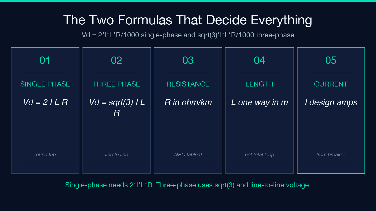
Voltage drop is Ohm’s law applied to a wire: current times resistance. For a DC or single-phase AC circuit, the drop is Vd = 2 I L R / 1000, where the leading factor of two accounts for the round trip (hot plus neutral). For a balanced three-phase circuit, the geometry changes and the formula drops to Vd = sqrt(3) I L R / 1000. The resistance R is in ohms per kilometer, L is one-way length in meters, and I is the design current in amps. Try it here with the default 15 A / 30 m / 12 AWG copper and you’ll see why: a 30 m 12 AWG copper run drops about 3.7 V single-phase, already 3% of a 120 V source.
That 3% threshold is not arbitrary. The NEC recommends — but does not strictly require — branch-circuit drops below 3% and feeder plus branch drops below 5% total. European IEC 60364 uses a similar 4% combined budget. Compliance is a percentage of the source voltage you feed in, which is exactly what the calculator’s compliance banner reports.
The conductor size that wins
Cross-sectional area is what governs resistance, not the bare wire diameter. AWG is a logarithmic scale where every three gauges doubles the area: 14 AWG is 2.08 mm², 12 AWG is 3.31 mm², 10 AWG is 5.26 mm². The calculator accepts either mode — pick AWG wire gauge for North American projects and metric mm² for IEC work — but never mix the two. A common mistake is to assume 1.5 mm² equals roughly 16 AWG; it’s closer to 14 AWG in resistance terms, and the difference shows up as a percent or two of drop.
The four compliance outcomes you’ll see
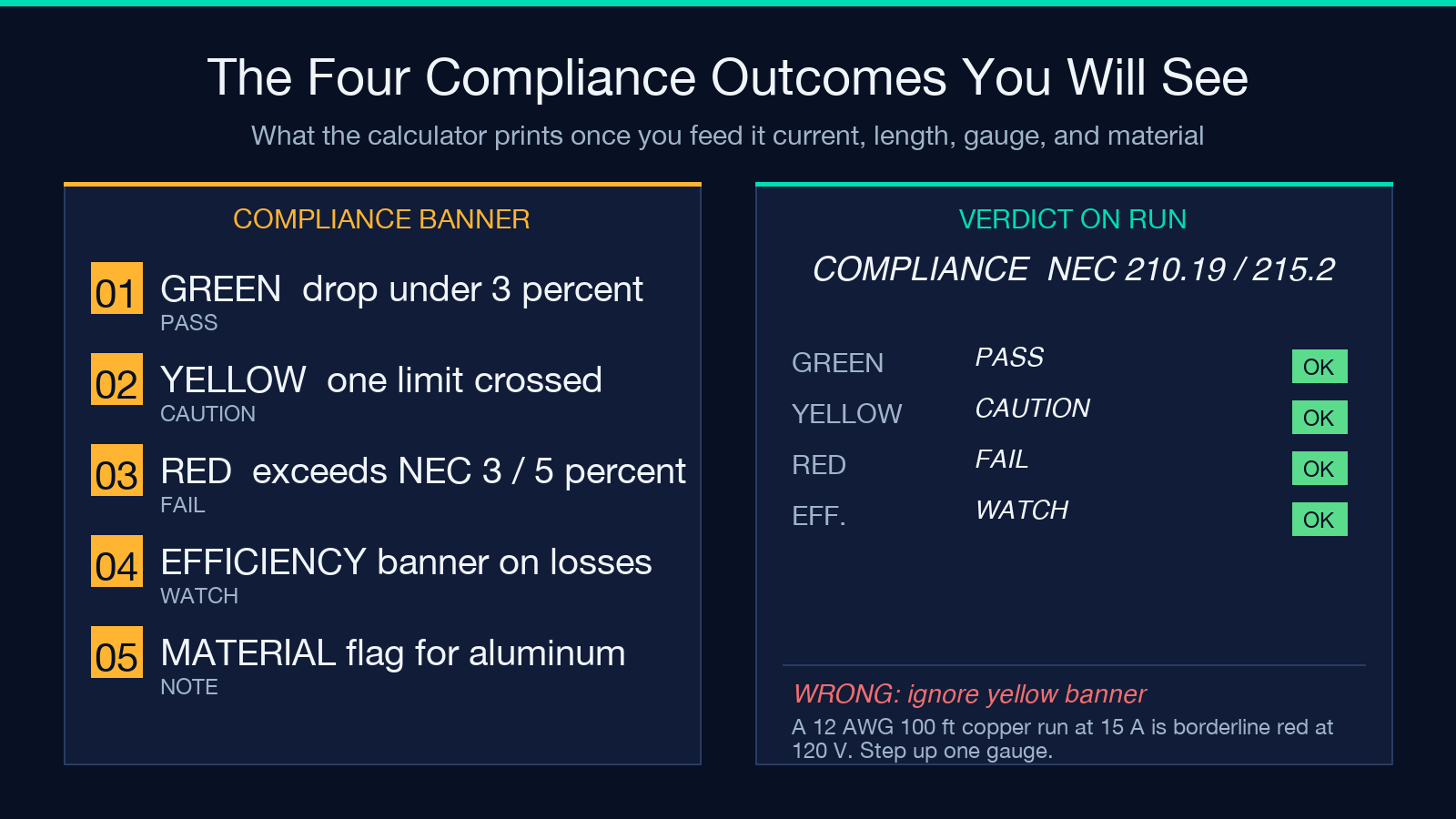
Feed the calculator a run and it labels the result one of four ways: green if both drop percent and end-of-line voltage meet target, yellow if you cross one but not the other, red if either exceeds the NEC soft limits, and a separate efficiency banner if the copper losses exceed 3% of delivered power. The efficiency banner matters for solar and battery work where every watt of loss is a watt you didn’t store — a 100 ft 12 AWG run at 20 A wastes 78 W as heat, which compounds across a year of runtime.
When to step up a gauge
The rule of thumb that saves more callbacks than any other: if your calculated drop is between 2.5% and 3.0% on a critical load (motors, LED drivers, electronics), step up one gauge. The cost difference is usually a few dollars per run; the callback cost is a service truck and a weekend. Long battery and inverter runs almost always need this bump — 24 V battery systems lose 6% across the same run that drops 3% at 120 V, which is why low-voltage DC circuits ship with surprisingly fat cables. For more on the underlying power math, the Ohm’s Law and Power Triangle Calculator covers the V = IR / P = VI / P = V²/R triangle, and the Voltage Divider Calculator is handy when you’re troubleshooting existing wiring and need to know what voltage actually arrives at the load.
Three-phase is not single-phase with a bigger number
The three-phase mode multiplies by sqrt(3) (1.732) instead of 2, and uses line-to-line voltage rather than line-to-neutral. If you mistakenly enter a 208 V three-phase run as a single-phase calculation, you’ll get a 30% inflated drop and over-size your conductor unnecessarily. If you go the other way and treat a 120 V single-phase run as three-phase, you’ll under-size and fail inspection. Always verify the calculator’s “Circuit Type” field matches the panel breaker label before you trust the answer.
Aluminum saves cost but costs performance
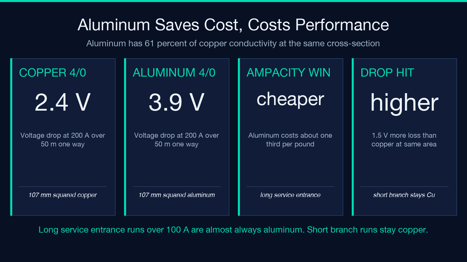
Aluminum has 61% of the conductivity of copper at the same cross-section, so a 4/0 aluminum run drops more than a 4/0 copper run at the same current. The trade is dollar-per-amp: aluminum is roughly a third of the price per pound, which is why service entrance cables larger than 4/0 are almost always aluminum in North American residential work. The calculator shows the difference directly — feed in 4/0 copper at 200 A over 50 m and you get a 2.4 V drop; switch the material to aluminum and the same geometry drops 3.9 V. If your panel is on the far end of a long driveway, that’s the difference between passing and failing.
Common pitfalls the calculator prevents
Three traps that hand-calculation always gets wrong: (1) using the wrong one-way length — the calculator wants the distance from panel to load, not the total cable run. A 100 ft loop of wire is 50 ft one-way. (2) Forgetting that 240 V circuits in the US are still single-phase in the calculator’s eyes (they share two hots and no neutral for line-line loads); the formula does not change, only the source voltage does. (3) Treating the conductor as if it operated at 25°C when it’s bundled in insulation that pushes it to 60°C or 75°C — the calculator uses the standard 75°C copper and 75°C aluminum resistance values from NEC table 9, which is the conservative reading inspectors expect.
Putting it together
Voltage drop is not a regulatory formality — it is a physics problem with a percentage budget, and every wire run you install is a transaction against that budget. The Cable Voltage Drop Calculator takes the four variables that matter (current, length, conductor area, material), applies the right formula for your circuit type, and prints the percentage plus the end-of-line voltage plus an efficiency banner so you can decide in one pass whether the run passes. Pair it with an ampacity check from your local code book and you’ve covered both halves of conductor sizing. For projects that mix solar, battery, and AC distribution, the same workflow works at every voltage tier — 12 V, 24 V, 48 V DC all the way up to 480 V three-phase — with only the source voltage changing. Browse related engineering tools in the Elysia Tools math and numbers collection when you need a sibling calculator like the power triangle or the voltage divider.