
Half a wavelength in air is exactly 180 degrees out of phase. Every dark fringe in a Young two-slit experiment is just an optical path difference of $\Delta = n \cdot d$ crossing the half-integer boundary, and the easiest way to read fringe maps, antireflection coating stacks, or thin-film interference is to convert the geometric path into $\Delta$ and then into the phase $\delta = 2\pi \cdot \Delta / \lambda_0$. The Optical Path Difference Calculator does that conversion in one pass and labels the regime as constructive, destructive, or intermediate, with an optional round-trip mode for the mirrors and thin films that fold the light back on itself.
This field guide explains what each output field means, when the round-trip mode flips a constructive fringe to a destructive one, and how to read the four-quadrant grid that shows up every time you have an unknown path on one arm and a known wavelength on the other.
What “Optical Path Difference” actually measures
Geometric path difference is just a length: 275 nm of extra air, 12 micrometers of extra glass, 1.4 millimeters of extra fused silica. Optical path difference weighs that length by the refractive index of the medium it travels through, so $\Delta = n \cdot d$. Two arms of an interferometer that are physically identical but one travels through BK7 glass ($n \approx 1.52$) instead of air ($n \approx 1.0003$) end up with very different $\Delta$ values even though $d$ is the same on both arms.
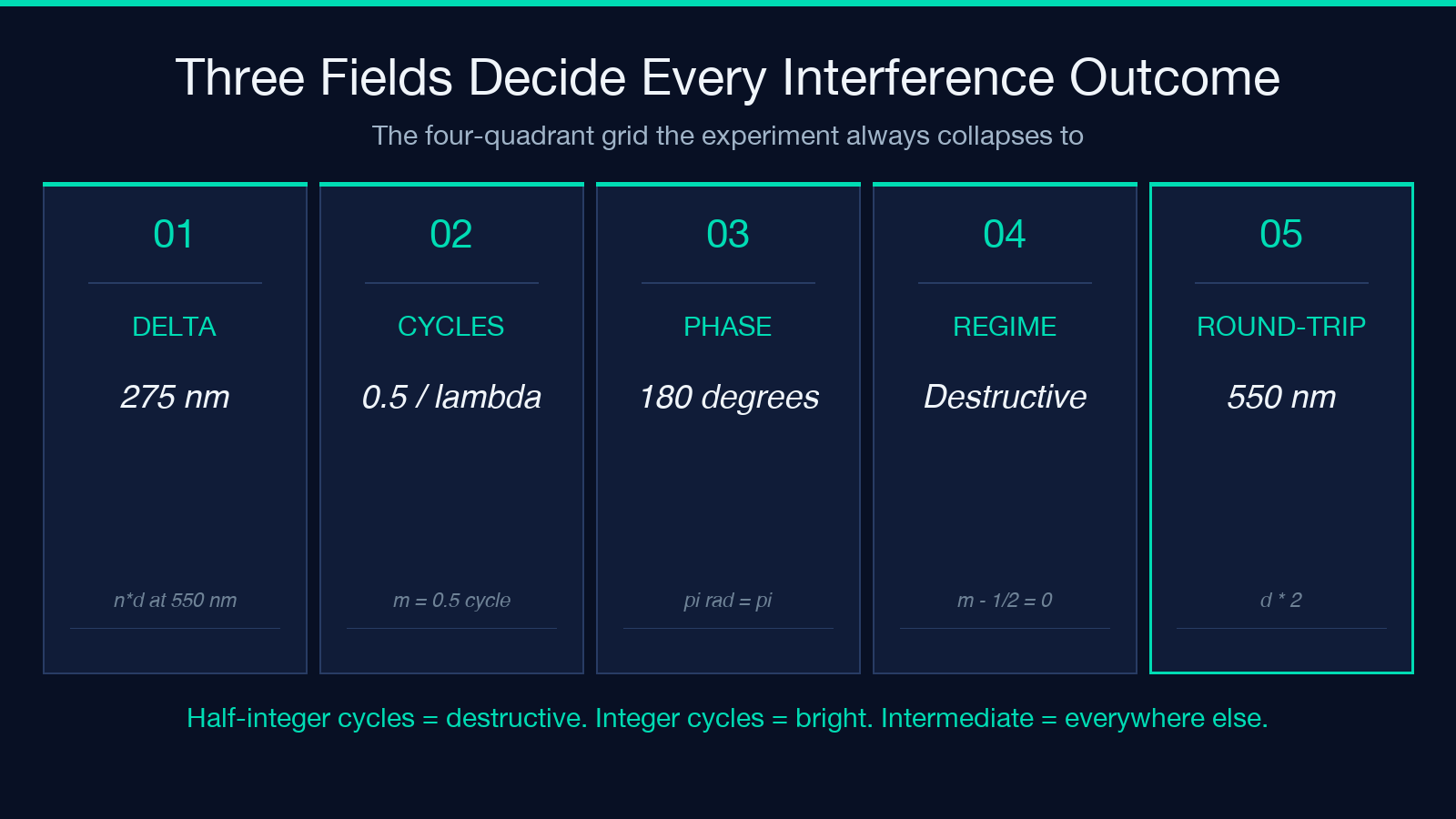
The calculator takes the geometric path, the refractive index, and the wavelength, and produces three fields:
$\Delta$ in nanometers (the optical path difference).
$\Delta / \lambda_0$ in cycles (how many wavelengths of delay).
$\delta$ in degrees or radians (the phase difference).
The regime label answers the only question most experiments care about: are the waves arriving in phase (constructive, bright) or out of phase (destructive, dark), and by how much?
A 275 nm extra air path against 550 nm green light is exactly $\lambda / 2$ in cycles, which is $\delta = 180°$ and the regime is destructive. That is the first dark fringe in the standard two-slit demo and the easiest sanity check you can run against the calculator.
Why $\Delta = n \cdot d$ and not just $d$
The “optical” qualifier matters because light slows down in denser media. The number of wavelengths that fit inside a 1 micrometer path of glass ($n = 1.52$) is 1.52 times the number that fit inside a 1 micrometer path of air, so two arms with the same geometric difference can produce different interference patterns if the medium differs. The classic Mach-Zehnder interferometer exploits this: a piece of glass in one arm shifts the fringe pattern even though both arms still have the same physical length.
The calculator treats $n$ as a single fixed scalar per arm. For most textbook setups that is enough: BK7 crown glass at 550 nm is $n \approx 1.519$, fused silica is $n \approx 1.461$, water is $n \approx 1.333$, and air at STP is $n \approx 1.00027$. For broadband or dispersion-sensitive work the index is wavelength-dependent and you need a Cauchy or Sellmeier model — that is outside the calculator’s single-$\lambda$ scope but the framework still applies: pick the wavelength of interest, look up $n(\lambda)$, feed both into the inputs.
How the regime label is decided
The calculator classifies the order $m = \Delta / \lambda_0$ into three buckets:
– Constructive when $m$ is an integer (0, 1, 2, …). Bright fringe.
Destructive when $m$ is a half-integer ($m
0.5 = 0, 1, 2, …$). Dark fringe.
Intermediate for everything in between.
The regime is what you actually need when you are tuning a thin-film stack or chasing a dark fringe on a screen. Half-integer $m$ is the bright-vs-dark toggle: 0.49 cycles is still bright (just below the dark fringe), 0.50 cycles is exactly dark, 0.51 cycles is climbing back toward bright.
For the half-wave plate case — the iconic 550 nm green against 275 nm air path — the order is 0.5 exactly and the calculator tags it as destructive. That single sample is the Optical Path Difference Calculator’s built-in example and it is the cleanest sanity check for any optical-path-difference workflow you build on top of it.
Round-trip mode for mirrors and thin films
Thin-film interference and Michelson interferometers are not single-pass: light reflects off a mirror and travels the same geometric path twice. The phase shift between the two reflected beams is governed by the round-trip path, not the single-pass path, so the calculator has a doublePass flag that doubles the effective geometric distance.
A quarter-wave antireflection coating on glass is a round-trip story: light enters, reflects off the back of the coating, exits, and the round-trip path through the coating layer must equal $\lambda / 4$ for the reflected and transmitted waves to cancel. With doublePass: true and a 550 nm wavelength, a coating thickness of $d = 137.5$ nm and $n \approx 1.38$ (MgF2) gives $\Delta \approx 379$ nm, which is just under $\lambda / 2$ in round-trip phase. That is the constructive/destructive crossover the coating designer is tuning for.
The same mode catches Fabry-Perot etalons, Sagnac interferometers, and any setup where the beam folds back on itself. Skip the toggle for Young two-slit (single pass); enable it for thin-film coatings, etalons, and any geometry with a return mirror.
Reading the four-quadrant output grid
The calculator’s output is laid out as a four-quadrant grid that compresses everything you need into one view:
– Top-left: the geometric path $d$ in the unit you entered.
Top-right: the wavelength $\lambda_0$ you matched against.
Bottom-left: $\Delta = n \cdot d$ and $\Delta / \lambda_0$ in cycles.
Bottom-right: $\delta$ in degrees and radians, plus the regime tag.
The quadrant that matters changes with the experiment. For fringe-spacing problems on a screen, the bottom-right quadrant tells you whether you are landing on a bright or dark band. For coating layer design, the bottom-left quadrant tells you whether your thickness is one-quarter wavelength or one-half wavelength. For phase-plate retarders, the bottom-right quadrant tells you whether the retarder is quarter-wave or half-wave — the difference between circularly polarized and linearly rotated output.
A 275 nm air path against 550 nm light reads “destructive, $180°$” in the bottom-right. A 1.4 micrometer extra glass path against 800 nm light reads “constructive, full cycle plus half, $180°$” — same phase, very different geometric path.
Three fringe problems the calculator collapses to one answer
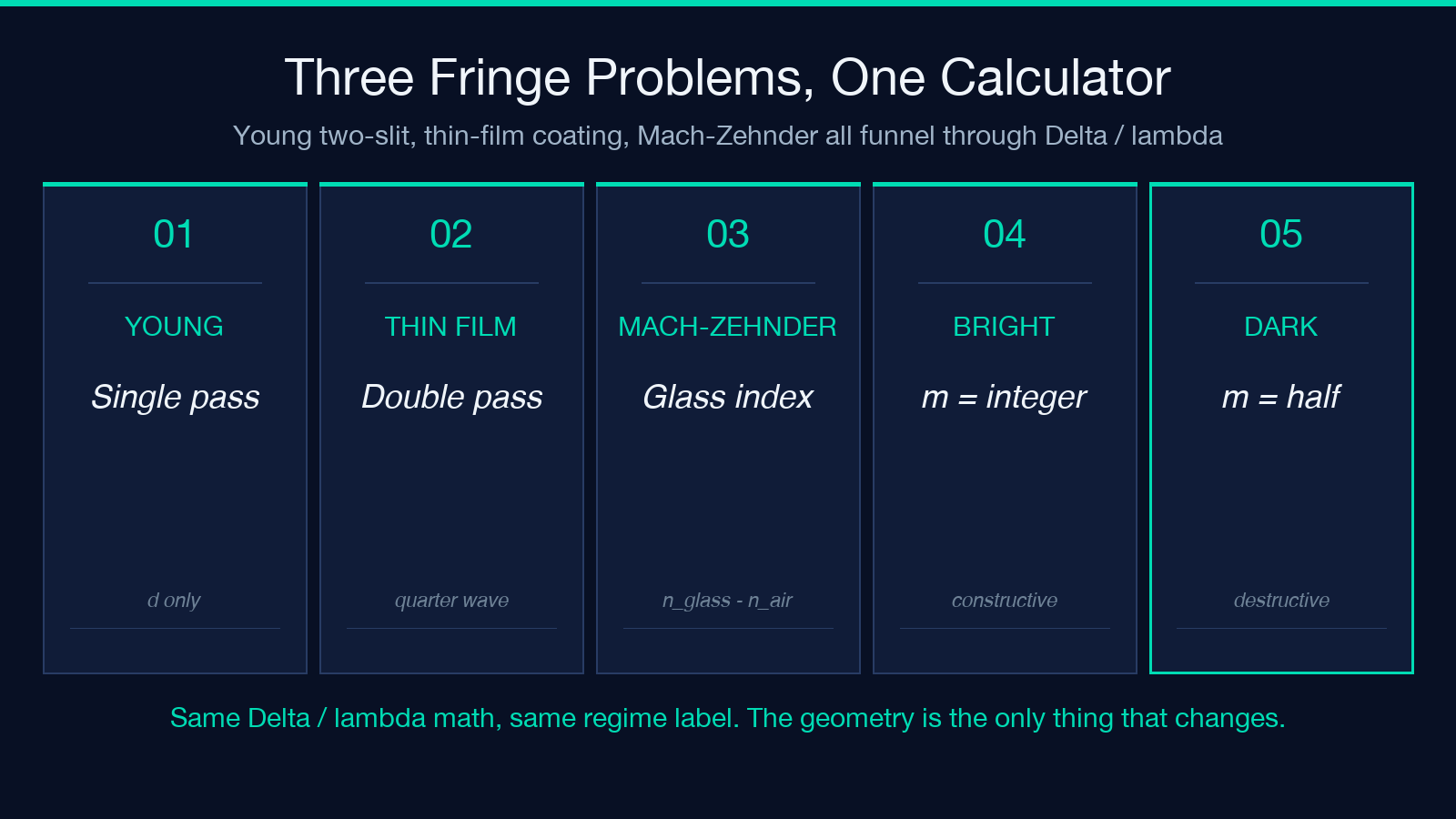
Three recurring interference setups all funnel through the same $\Delta / \lambda_0$ calculation:
– Young two-slit (single pass): fringe spacing on the screen is governed by the geometric path difference across adjacent slits, and the bright/dark sequence is just $\Delta / \lambda_0 = m$ vs $m + 0.5$.
Thin-film coating (double pass): quarter-wave thickness is $\Delta = \lambda / 4$ for the round-trip path through the coating; half-wave thickness is $\Delta = \lambda / 2$.
Mach-Zehnder (single or double pass depending on geometry): an extra piece of glass shifts $\Delta$ by $(n_{\text{glass}}
n_{\text{air}}) \cdot d$, and the fringe pattern shifts accordingly.
The calculator does not care which geometry you are running — it just asks for $d$, $n$, $\lambda_0$, and whether to double. You can run all three setups through the same tool and get the same regime label that the experiment produces on screen.
When the regime label surprises you
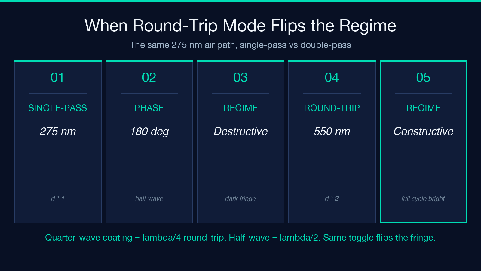
The most common surprise is round-trip vs single-pass. A 275 nm path with doublePass: true against 550 nm light gives $\Delta = 550$ nm, $\Delta / \lambda_0 = 1.0$ cycle, regime constructive — the same physical setup that was destructive single-pass is constructive round-trip. Always check the toggle before reading the regime.
The second surprise is the refractive index. A piece of glass that you might call “1 mm thick” in lab notes is $n \approx 1.52$ times that in optical-path terms, so a 1 mm BK7 plate is roughly 1.52 mm of optical path. The geometric and optical paths only agree when $n = 1$ (vacuum or, to four decimal places, air).
The third surprise is precision. Optical path calculations are sensitive to the third decimal of $\lambda_0$ and the second decimal of $n$. A 1% index error at $\Delta / \lambda_0 = 0.5$ (the dark fringe) is enough to flip the regime from destructive to intermediate. Use the most precise $n$ and $\lambda_0$ you have for the medium of interest, not generic textbook values.
Putting it all together
The Optical Path Difference Calculator is the missing link between the geometric layout of an interferometer and the bright/dark pattern on the screen. Feed it the path, the index, the wavelength, and whether the light bounces back on itself, and it returns the three fields that decide every interference outcome: $\Delta$, $\Delta / \lambda_0$, and $\delta$ plus the regime tag. Run the Optical Path Difference Calculator once on the standard 275 nm / 550 nm dark-fringe case to anchor your intuition, then drop your own experiments into the same four-quadrant grid and read the regime label first.
