
Most cam calculators hand you a number for follower lift, and that’s where the trouble starts. The figure you actually need is not the lift — it is whether that lift happens at a velocity and acceleration your mechanism can survive, and whether the contact force stays inside a pressure angle your return spring can hold. A cam-follower displacement calculator that reports all four (displacement, velocity coefficient, acceleration coefficient, pressure angle) for constant-velocity, constant-acceleration, harmonic, and cycloidal motion laws is the only kind worth running, because the choice of motion law is most of the design. Switch from constant velocity to cycloidal and your peak acceleration drops by nearly 40 percent for the same rise time, which is the difference between a follower that chatters and one that rides clean.
What a Cam-Follower Displacement Calculator Actually Computes
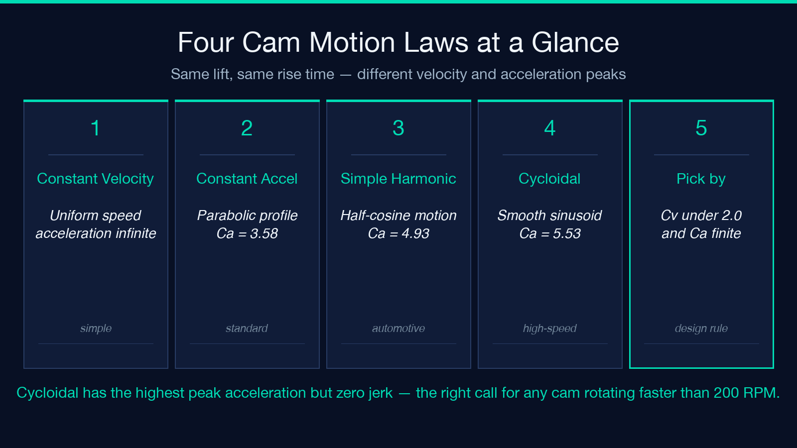
At its core, a cam-follower displacement calculator gives you the same five numbers for every motion law: the follower position s(θ) at any cam angle θ, the peak velocity v_max, the peak acceleration a_max, the velocity coefficient C_v = v_max × T / h, and the acceleration coefficient C_a = a_max × T² / h. The last two are dimensionless — they let you compare motion laws independent of the rise time T and the lift h, which is why cam-design textbooks have the same coefficient table on page 47 in every edition since 1958.
The peak velocity and acceleration matter because they drive the contact force between cam and follower, and contact force is what wears the cam. The pressure angle matters because, for an in-line radial roller follower, it is the angle between the direction of follower motion and the normal to the cam profile at the contact point. Above roughly 30 degrees the return spring force grows faster than the cam-driving force component, and the follower jumps off the cam. Most cam calculators estimate pressure angle with the in-line radial approximation tan(φ) ≈ (ds/dθ − e) / (s + r_r + sqrt(r_b² − e²)), where e is the offset, r_r the roller radius, and r_b the base-circle radius.
The Four Motion Laws and Where Each One Wins
Constant-velocity motion is the simplest: the follower moves at uniform speed during rise and return. The displacement curve is a straight ramp, the velocity curve is a square pulse, and the acceleration curve is two Dirac impulses at the start and end of rise. That last point is why constant velocity is almost never the right choice for a real cam — the infinite theoretical acceleration means infinite force, which means infinite wear, which means a cam that lasts about four hours. Use it only for slow, low-load applications where the cam is doing something simple like opening a valve once per cycle.
Constant-acceleration motion (also called parabolic motion because the displacement is a parabolic segment) is the textbook default. Velocity rises and falls linearly, acceleration is constant in two segments with a step discontinuity in the middle, and the velocity coefficient C_v = 2 regardless of lift or rise time. The acceleration step is a real problem for high-speed cams because it excites vibrations at the step frequency. Cycloidal motion eliminates the acceleration step entirely — acceleration is a continuous sinusoid — and is the standard choice for high-speed machine-tool cams and automatic-weapon receivers where smoothness is non-negotiable.
Simple harmonic motion (SHM) uses half a cosine wave. The acceleration coefficient C_a ≈ 4.93, between parabolic (3.58) and cycloidal (5.53). SHM is what most automotive valve cams in textbooks use, because the math is clean and the cam-grinder can grind it. For modern high-RPM engines, cycloidal wins because its lower velocity coefficient at the dwell transitions reduces follower jump at the nose. The Elysia tool at elysiatools.com/en/tools/cam-follower-displacement reports all four laws side by side so you can pick by coefficient, not by feel.
Setting Up the Geometry Without Blowing the Pressure Angle
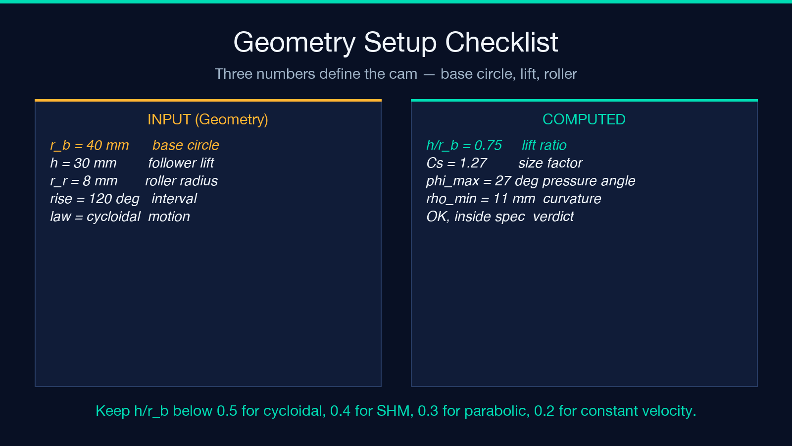
Three numbers define the geometry: base-circle radius r_b, lift h, and roller radius r_r. The pressure angle is most sensitive to the ratio h / r_b. For a 50 mm base circle and a 50 mm lift, the peak pressure angle on cycloidal motion at a 120-degree rise is already past 32 degrees — over the limit. Halve the lift to 25 mm and the same geometry gives 22 degrees, comfortably inside spec. The rule of thumb: keep h / r_b < 0.5 for cycloidal, less than 0.4 for SHM, less than 0.3 for parabolic, less than 0.2 for constant velocity.
The roller radius does not affect the pressure angle directly, but it controls undercut. When the cam profile curvature becomes smaller than the roller radius, the profile self-intersects and the cam becomes un-grindable. For a disc cam with a translating roller follower, the minimum profile radius of curvature is ρ_min = (r_b + s + r_r)³ / ((r_b + s + r_r)² + (ds/dθ)²)⁻¹ − r_r. The factor inside the cube is the distance from cam center to roller center, and the derivative term is the velocity coefficient scaled. For any motion law, the steepest part of the displacement curve is where undercut is most likely.
An offset follower shifts the roller off the cam-center line by an amount e, which can reduce peak pressure angle by 10 to 15 percent when the offset is placed on the side of the cam where the rise is gentler. The trade-off is asymmetry: the return side now has higher pressure angle than the rise side. Most production cams are symmetric (zero offset) for manufacturing simplicity, and the motion law is chosen to bring pressure angle inside spec instead.
Reading the Coefficient Tables the Right Way
The coefficient table looks like four rows of harmless numbers until you realize the same coefficient table appears in every cam-design reference from Chen and Pollack in the 1960s to the current Machinery’s Handbook. The numbers are universal because they are derived from the motion law’s normalized shape, not from any specific cam. Cycloidal: C_v = 2.0, C_a = 5.53. Parabolic (constant-acceleration): C_v = 2.0, C_a = 3.58. SHM: C_v = π/2 ≈ 1.57, C_a = π²/2 ≈ 4.93. Constant velocity: C_v = 1.0, C_a = ∞ (which is the entire reason you do not use it).
The right way to read the table is: pick C_v and C_a you can tolerate, then back-solve for the maximum cam speed. Given a 30 mm lift, a 0.05 s rise, and a tolerance for C_a = 5.53 (cycloidal), the peak acceleration is a_max = C_a × h / T² = 5.53 × 0.030 / 0.0025 = 66.4 m/s². That is 6.8 g. For a 0.5 kg follower, peak inertial force is 33 N — well within a small return spring. Same lift with parabolic motion gives C_a = 3.58, so a_max = 43 m/s² (4.4 g), but the acceleration is a square wave with infinite jerk at the transitions. For a precision indexing cam the cycloidal motion law costs you 50 percent more peak force but eliminates the jerk-driven ringing that ruins positional accuracy.
When Constant Velocity Is the Wrong Default
Constant-velocity motion has one genuine use case: low-speed, low-inertia cams where the goal is uniform dwell at the top of the lift. A drop-hammer release cam, a slow-closing pneumatic valve, an indexing fixture cam running at under 100 RPM — in each case the cam is doing mechanical work that does not depend on smooth motion, and the simplicity of a straight ramp on the displacement diagram is worth the theoretical infinite acceleration at the corners. The infinite acceleration never manifests in practice because the dwell adds at the corner and rounds it; the cam is doing what a constant-velocity cam does, but with finite acceleration at the corners because no real cam has a zero-duration dwell.
The trap is reaching for constant velocity because it is the default in CAD libraries and spreadsheet macros. Every spreadsheet cam-design template shipped since Lotus 1-2-3 has a constant-velocity column. Most of those templates were written by mechanical engineers who used them for slow cams where the choice did not matter. The same template copied into a 3000 RPM automotive valve cam will give a follower that jumps off the cam at every transition and a service life measured in shifts, not years. Before you run a constant-velocity cam, ask: is the cam rotating slowly enough that the dwell transition happens over more than 5 milliseconds? If yes, constant velocity is fine. If no, switch to cycloidal.
Tracing a Worked Example Through Rise, Dwell, and Return
Take a disc cam with a translating roller follower. Base-circle radius 40 mm, roller radius 8 mm, lift 30 mm, total cam rotation 360 degrees. Motion plan: rise over 120 degrees, dwell high for 60 degrees, return over 120 degrees, dwell low for 60 degrees. Cycloidal motion law for rise and return. The tool at elysiatools.com/en/tools/cam-follower-displacement computes the displacement at every 10-degree step.
At cam angle 0 the follower is at the base circle (lift = 0). At 60 degrees into the rise the follower is at 15 mm (half-lift, because cycloidal motion is symmetric around half-rise). At 120 degrees the follower is at 30 mm (full lift). Peak velocity occurs at 30 and 90 degrees into the rise, both at v_max = C_v × h / T = 2.0 × 0.030 / (T) where T is the rise time. Peak acceleration occurs at 0, 60, and 120 degrees into the rise — the start, midpoint, and end of the rise. Pressure angle peaks at the same points as peak velocity for an in-line radial follower.
The numerical values matter less than the shape of the curves: cycloidal motion gives a smooth bell for displacement, a smooth sinusoid for velocity, and a smooth cosine for acceleration. No discontinuities. Compared to parabolic motion (which has a velocity triangle and an acceleration step at mid-rise), cycloidal is what you want for any cam rotating faster than about 200 RPM or driving a follower with appreciable mass.
Three Pressure-Angle Traps That Push a Design Past 30 Degrees
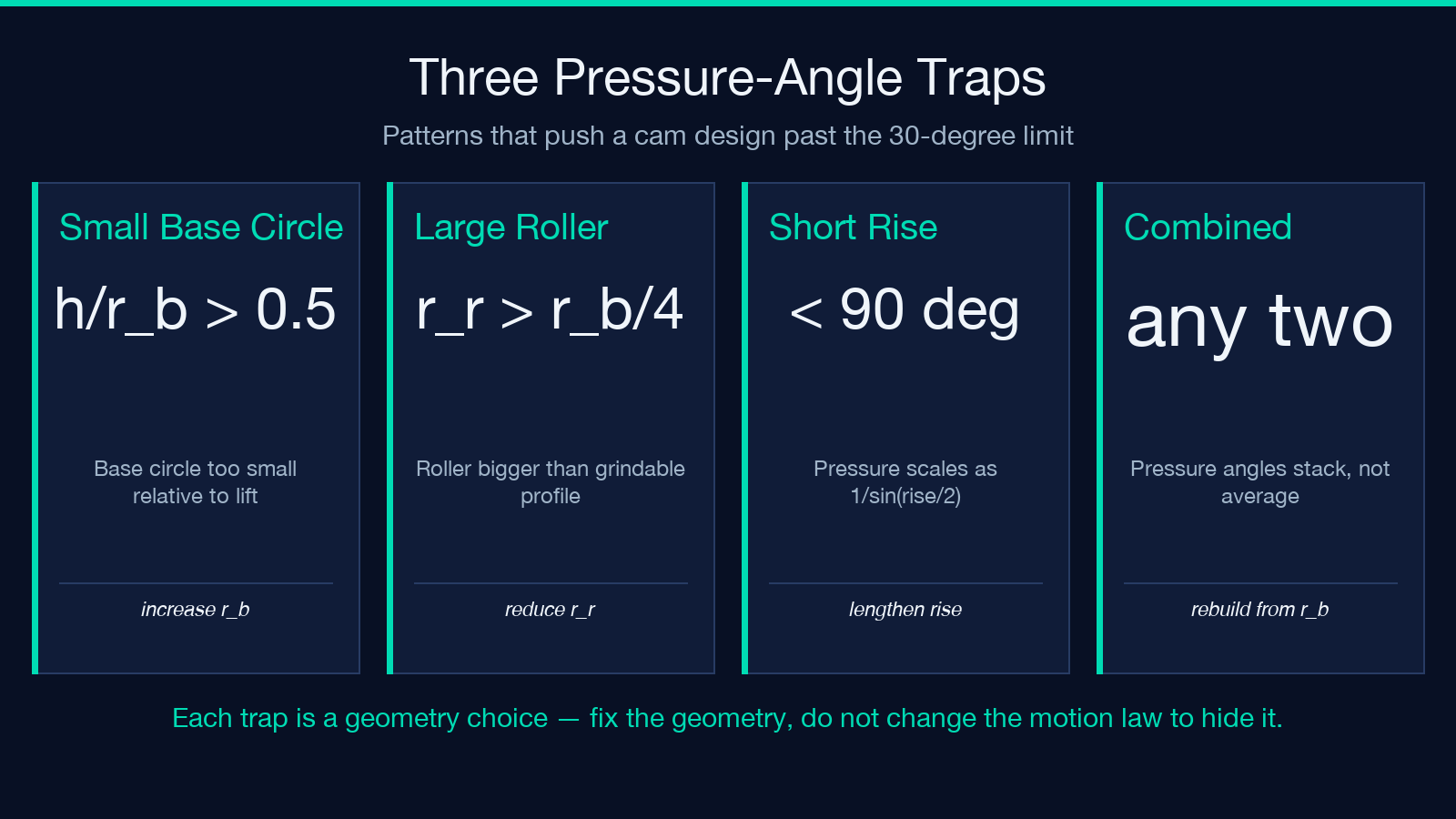
The first trap is a small base circle relative to the lift. A 30 mm base circle and a 25 mm lift (ratio 0.83) on cycloidal motion at a 90-degree rise gives a peak pressure angle of 45 degrees — the return spring cannot hold the follower on the cam. The fix is to increase the base circle until h / r_b < 0.5. For the same 25 mm lift that means r_b > 50 mm. A larger base circle costs material and inertia but is the only mechanical fix.
The second trap is a too-large roller. A 20 mm roller on a 40 mm base-circle cam (half the radius) cuts the grindable profile region in half because the minimum radius of curvature has to exceed the roller radius. The cam profile is mathematically smooth, but no grinding wheel can produce it. The fix is to reduce the roller radius or change the cam proportions so the profile curvature is larger everywhere.
The third trap is the rise interval. The textbook 120-degree rise works for symmetric disc cams, but if you need a faster cycle you shrink the rise to 90 degrees. The pressure angle scales roughly as 1 / sin(α_rise / 2), so halving the rise interval from 120 to 60 degrees raises the peak pressure angle by about 40 percent. The tool at elysiatools.com/en/tools/cam-follower-displacement lets you hold one variable constant and sweep the other to find the combination that keeps pressure angle inside the 30-degree limit.
Plugging Your Numbers Into Elysia and Auditing the Output
Open the cam-follower displacement calculator at elysiatools.com/en/tools/cam-follower-displacement, enter base-circle radius, lift, rise interval, return interval, and roller radius, and select all four motion laws. The output is a table of s, v, a, and pressure angle at every cam-angle step, plus a plot. The audit question is the same one a cam-design review would ask: are the pressure-angle peaks for all four motion laws under 30 degrees, and is the minimum profile radius of curvature greater than the roller radius everywhere on the cam profile?
If pressure angle is over 30 degrees on the law you wanted, do not move to a faster cam and hope. The motion law’s C_v is fixed by the law itself; the pressure angle is controlled by the geometry and the rise interval. Either the base circle is too small, or the rise interval is too short, or the lift is too large. Adjust one at a time and re-run the calculator until the peak pressure angle drops under 30 degrees for all motion laws you are considering. The four-law side-by-side comparison is the part no spreadsheet cam-design template gives you, and the part that prevents the constant-velocity default from ruining a high-speed design.
